NOTE: To read this article, you need a basic understanding of L2VPN, AToM (Any Transport over MPLS) and Pseudowire technologies.
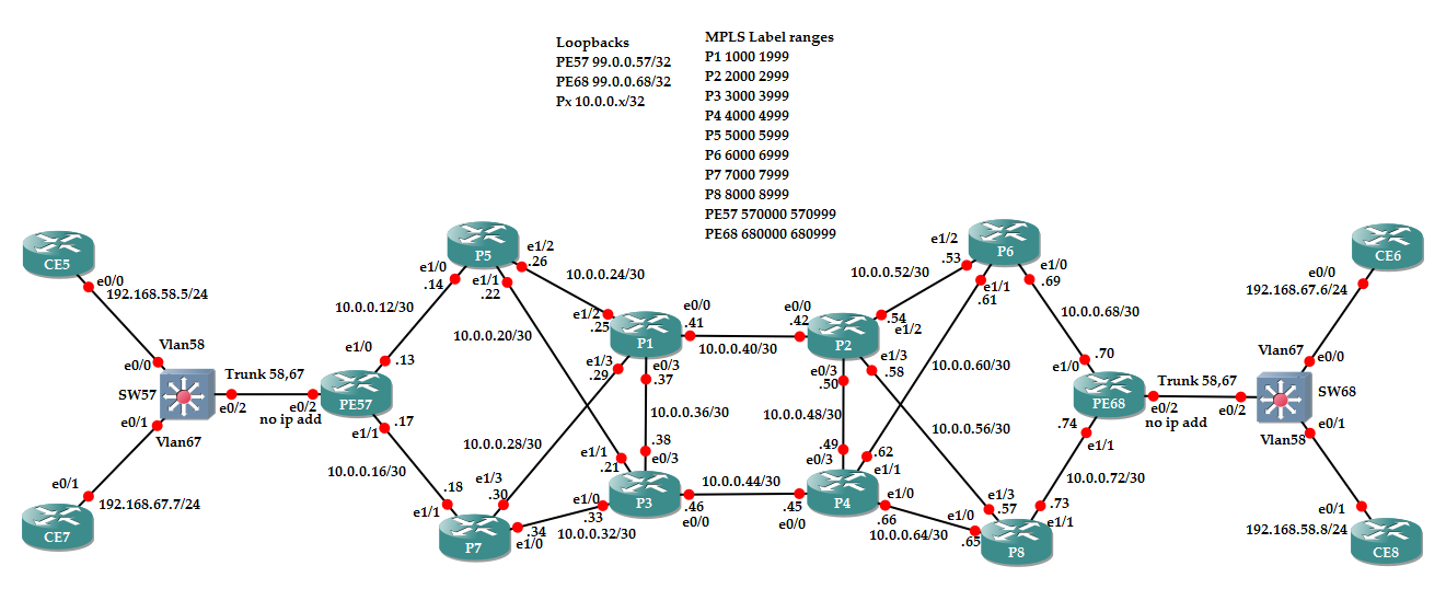
What happens when an Ingress PE configured for L2VPN services, then supporting Pseudowires (PWs), has more than one IGP path to reach the Loopback of the Egress PE? We know that Pseudowires are made of TWO unidirectional Label Switch Paths (LSPs), one going from PEx to PEy and the other one going in the opposite direction from PEy to PEx. Let’s consider this topology
Now, look how PE57 and PE68 see each other Loopback:
PE57#show ip cef 99.0.0.68
99.0.0.68/32
nexthop 10.0.0.14 Ethernet1/0 label 5000
nexthop 10.0.0.18 Ethernet1/1 label 7000
PE57#show mpls forwarding-table 99.0.0.68
Local Outgoing Prefix Bytes Label Outgoing Next Hop
Label Label or Tunnel Id Switched interface
570002 5000 99.0.0.68/32 0 Et1/0 10.0.0.14
7000 99.0.0.68/32 0 Et1/1 10.0.0.18
PE68#show ip cef 99.0.0.57
99.0.0.57/32
nexthop 10.0.0.69 Ethernet1/0 label 6021
nexthop 10.0.0.73 Ethernet1/1 label 8021
PE68#show mpls forwarding-table 99.0.0.57
Local Outgoing Prefix Bytes Label Outgoing Next Hop
Label Label or Tunnel Id Switched interface
680024 6021 99.0.0.57/32 0 Et1/0 10.0.0.69
8021 99.0.0.57/32 0 Et1/1 10.0.0.73
I know that to establish a Pseudowire a two-level mpls label stack is needed, where the outer label (aka the Tunnel Label) will be the label used by PEs to reach the Loopback of the remote Egress PE. In this scenario both PEs has two possible outer labels because OSPF has two equal cost paths, will be the traffic moved down the Pseudowire load shared too?
Let’s configure a Pseudowire with ID 58 between PE57 and PE68
PE57#show run int e0/2.58 | b interface
interface Ethernet0/2.58
encapsulation dot1Q 58
xconnect 99.0.0.68 58 encapsulation mpls
PE68#sh run int e0/2.58 | b interface
interface Ethernet0/2.58
encapsulation dot1Q 58
xconnect 99.0.0.57 58 encapsulation mpls
With this basic configuration I enabled the Virtual Channel (VC) 58 between the two PEs:
PE57#show mpls l2transport vc 58
Local intf Local circuit Dest address VC ID Status
————- ————————– ————— ———- ———-
Et0/2.58 Eth VLAN 58 99.0.0.68 58 UP
PE57#show mpls l2transport vc 58 detail | i stack
Output interface: Et1/0, imposed label stack {5000 680000}
PE68#show mpls l2transport vc 58
Local intf Local circuit Dest address VC ID Status
————- ————————– ————— ———- ———-
Et0/2.58 Eth VLAN 58 99.0.0.57 58 UP
PE68#show mpls l2transport vc 58 detail | i stack
Output interface: Et1/0, imposed label stack {6021 570000}
From the above output you can see that PE57 choose P5 (label 5000) as next-hop router for Pseudowire 58 and PE68 chooses P6 (label 6021). What happens to the traffic when it reach the P routers in the core, in terms of used links to reach the egress PE, it’s not easy to say, because Label Switched Path (LSPs) are someway splitted because labels are assigned by LDP based on IGP (OSPF in this case), and I have more than one IGP equal cost path, for example when P5 receives a Labeled Packet and the top label is 5000 it has two choices:
P5#show mpls forwarding-table 99.0.0.68
Local Outgoing Prefix Bytes Label Outgoing Next Hop
Label Label or Tunnel Id Switched interface
5000 3000 99.0.0.68/32 69244 Et1/1 10.0.0.21
1000 99.0.0.68/32 0 Et1/2 10.0.0.25
Then, we cannot be sure about which is the path followed in the core, this is not a problem specific to L2VPN traffic but it is something that happens for any MPLS application based on Labels distributed by LDP/IGP.
Let’s send some ping traffic on the Pseudowire and let’s check which is the path, capturing the packets on the involved links. CE5 and CE8 should be able to talk to each other transporting their traffic over Vlan58 configured on switches 57 and switch 68, VLAN should be extended between the remote sites using the L2VPN service offered by the Provider using Pseudowire58. At the beginning, no traffic flows between CE5 and CE8 so they cannot know their respective MAC addresses:
CE5#sh ip arp
Protocol Address Age (min) Hardware Addr Type Interface
Internet 192.168.58.5 – aabb.cc00.0100 ARPA Ethernet0/0
CE8#show ip arp
Protocol Address Age (min) Hardware Addr Type Interface
Internet 192.168.58.8 – aabb.cc00.0e10 ARPA Ethernet0/1
Sending some ping packets between the twos I see:
CE5#ping 192.168.58.8
Type escape sequence to abort.
Sending 5, 100-byte ICMP Echos to 192.168.58.8, timeout is 2 seconds:
.!!!!
Success rate is 80 percent (4/5), round-trip min/avg/max = 5/10/19 ms
CE5#show ip arp
Protocol Address Age (min) Hardware Addr Type Interface
Internet 192.168.58.5 – aabb.cc00.0100 ARPA Ethernet0/0
Internet 192.168.58.8 0 aabb.cc00.0e10 ARPA Ethernet0/0
CE8#show ip arp
Protocol Address Age (min) Hardware Addr Type Interface
Internet 192.168.58.5 0 aabb.cc00.0100 ARPA Ethernet0/1
Internet 192.168.58.8 – aabb.cc00.0e10 ARPA Ethernet0/1
Above outputs confirm that CE5 and CE8 can see each other as if they were directly connected. Let’s check the path followed by the icmp packets. In the following picture I described how arp request/reply and icmp packets are distributed among all physical links between Ingress and Egress PEs while traversing the Core of P routers.
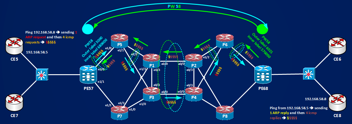
It can be seen that arp request and icmp requests follow a different path in the core from the one followed by arp and icmp replies. Then I can say that PEs associates a link toward the core to a Pseudowire, then P routers being unaware of the presence of a pseudowire will do a traffic distribution based on their normal cef load sharing algorithm. In other words the Pseudowire is spllitted in two unidirectional LSPs in the core and, by default, you cannot be sure that the the two paths are the same, then you can see links more utilized in one direction with respect to the opposite direction of the traffic. Normally this splitting of direct and return traffic in the core is not a problem for many applications, anyway this can be considered a first level of traffic splitting (let’s call it intra-pw traffic splitting) for a single Pseudowire and this effect is not Pseudowire/L2VPN specific but it exists for any MPLS applications based on P routers that are unaware of the specific mpls traffic application they are switching.
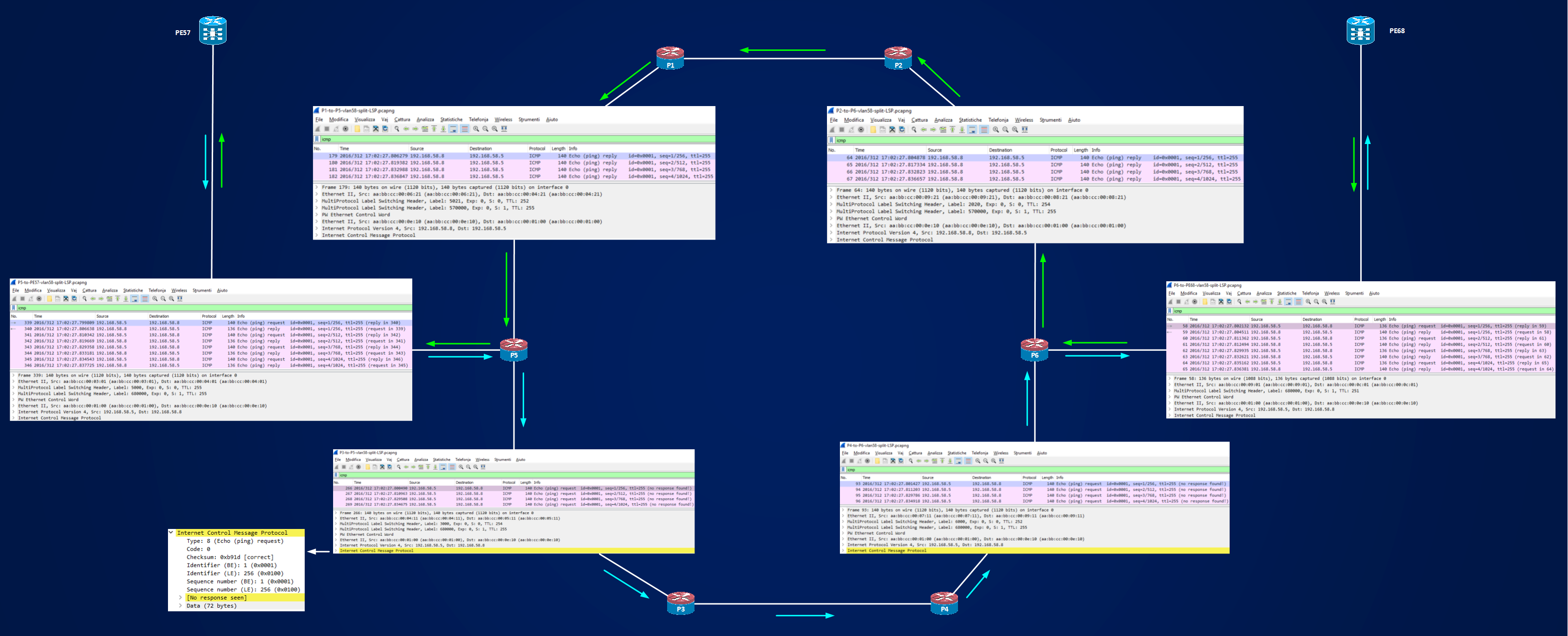
Here I collected some snapshots of the captured packets that confirms how requests and replies follow a different paths:
A second level of traffic splitting exists at PEs when there are multiple Pseudowire configured, let’s call it inter-PW traffic splitting, for example let’s add a second Pseudowire (number 67) between PE57 and PE68, this Pseudowire will transport the traffic of CE connected on VLAN67 at customers’ switches:
CE7#sh ip arp
Protocol Address Age (min) Hardware Addr Type Interface
Internet 192.168.67.7 – aabb.cc00.0b10 ARPA Ethernet0/1
CE6#show ip arp
Protocol Address Age (min) Hardware Addr Type Interface
Internet 192.168.67.6 – aabb.cc00.0d00 ARPA Ethernet0/0
PE57#sh run int e0/2.67 | b interface
interface Ethernet0/2.67
encapsulation dot1Q 67
xconnect 99.0.0.68 67 encapsulation mpls
PE68#sh run int e0/2.67 | b interface
interface Ethernet0/2.67
encapsulation dot1Q 67
xconnect 99.0.0.57 67 encapsulation mpls
PE57#show mpls l2transport vc 67
Local intf Local circuit Dest address VC ID Status
———— ————————– ————— ———- ———-
Et0/2.67 Eth VLAN 67 99.0.0.68 67 UP
PE68#show mpls l2transport vc 67
Local intf Local circuit Dest address VC ID Status
————- ————————– ————— ———- ———-
Et0/2.67 Eth VLAN 67 99.0.0.57 67 UP
PE57#show mpls l2transport vc 67 detail | i stack
Output interface: Et1/1, imposed label stack {7008 680001}
PE68#show mpls l2transport vc 67 detail | i stack
Output interface: Et1/1, imposed label stack {8010 570001}
Compare the output interfaces of PW67 with the ones of PW58:
PE57#show mpls l2transport vc 58 detail | i stack
Output interface: Et1/0, imposed label stack {5000 680000}
PE68#show mpls l2transport vc 58 detail | i stack
Output interface: Et1/0, imposed label stack {6021 570000}
It’s easy to see that PEs choose different interfaces among the available twos to exit toward the backbone, PW58 is linked to e1/0, PW67 is linked to e1/1. This is a general rule, when there are multiple possible exit interfaces toward the backbone and there are multiple Pseudowires, Pseudowires are rounded-robin on the available interfaces. Here I have two possible interfaces on PEs e1/0 and e1/1. If now I add a third and fourth Pseudowire they will be distributed among e1/0 and e1/1:
PE57#sh mpls l2 vc 58 detail | i stack
Output interface: Et1/0, imposed label stack {5016 680000}
PE57#sh mpls l2 vc 67 detail | i stack
Output interface: Et1/1, imposed label stack {7002 680001}
PE57#sh mpls l2 vc 158 detail | i stack
Output interface: Et1/0, imposed label stack {5016 680026}
PE57#sh mpls l2 vc 157 detail | i stack
Output interface: Et1/1, imposed label stack {7002 680025}
PE68#sh mpls l2 vc 58 detail | i stack
Output interface: Et1/0, imposed label stack {6018 570000}
PE68#sh mpls l2 vc 67 detail | i stack
Output interface: Et1/1, imposed label stack {8017 570001}
PE68#sh mpls l2 vc 158 detail | i stack
Output interface: Et1/0, imposed label stack {6018 570026}
PE68#sh mpls l2 vc 157 detail | i stack
Output interface: Et1/1, imposed label stack {8017 570025}
PE57#show mpls l2transport summary
Destination address: 99.0.0.68, total number of vc: 4
0 unknown, 4 up, 0 down, 0 admin down, 0 recovering, 0 standby, 0 hotstandby
2 active vc on MPLS interface Et1/0
2 active vc on MPLS interface Et1/1
PE68#show mpls l2transport summary
Destination address: 99.0.0.57, total number of vc: 4
0 unknown, 4 up, 0 down, 0 admin down, 0 recovering, 0 standby, 0 hotstandby
2 active vc on MPLS interface Et1/0
2 active vc on MPLS interface Et1/1
Note that each PE chooses independently how to link each Pseudowires to the exit interface toward the backbone. To choose the exit interface when equal cost multipaths exist, PE uses an hashing function that uses the VC label of the pseudowire, in my example the labels are 680000 680001 680025 680026 imposed by PE68 and used on PE57 and 570000 570001 570025 570026 imposed by PE57 and used on PE68.
Now, can we have a stronger control on the path that packets sent down on a pseudowire take after the PEs and inside the core? Yes, the option is to configure preferred-path.
Preferred-path gives me the possibility to have control on which interface is attached to the pseudowire on the PE routers and can be configured in two different way, using IGP routing and using MPLS Traffic-Engineering.
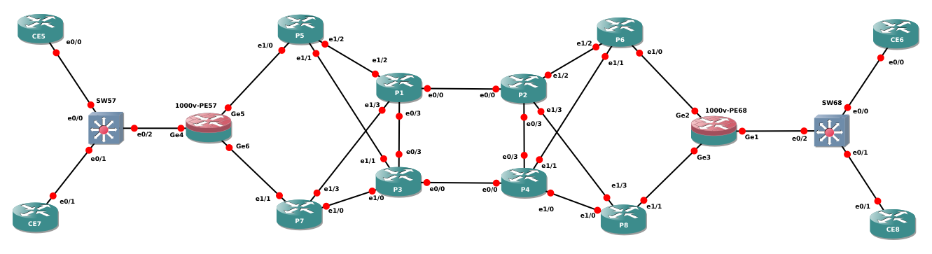
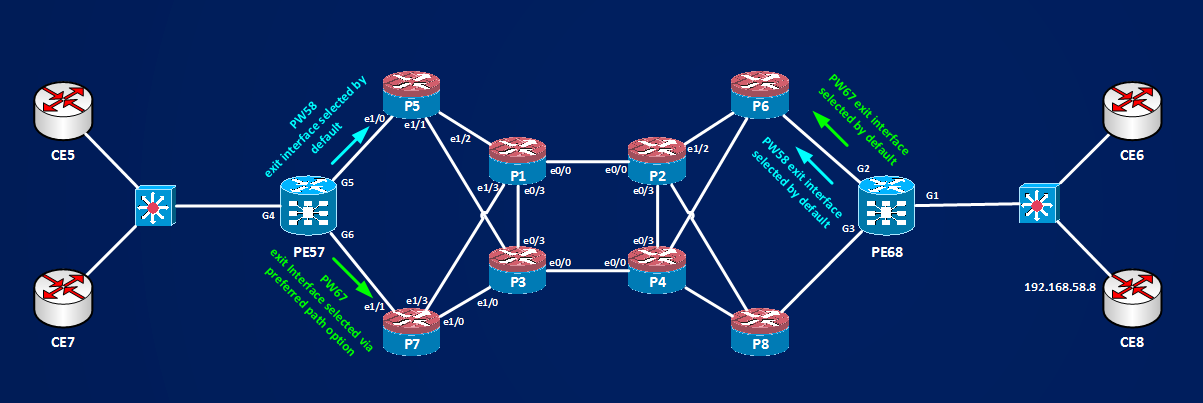
To use preferred-path option I have to replace the PEs with CSR1000v VMs to have support for the command, new topology is this one, all IPs are the same of the previous test:
Now, for what I learned so far, Pseudowires target the Remote PE’s Loopbacks to establish, then the xconnect command has this PE’s Loopback address as parameter. To have a preferred path different from the default one, a possibility is to have multiple Loopbacks interfaces on the remote PEs and to configure the IGP in such a way that different Loopbacks are seen at different next-hop interfaces. To do this you can play with IGP costs, offset-lists, distribute-list and/or using any other available tool to influence IGP decisions, doing such a thing is not something really scalable or adaptable in a medium/large network, anyway I will do a short example using static routes.
To use preferred-path option you need to configure a pseudowire class:
1000v-PE57#sh run | s pseudo
pseudowire-class PW58
encapsulation mpls
pseudowire-class PW67
encapsulation mpls
1000v-PE68#sh run | s pseudo
pseudowire-class PW58
encapsulation mpls
pseudowire-class PW67
encapsulation mpls
1000v-PE57#sh run int g4.58 | b interface
interface GigabitEthernet4.58
encapsulation dot1Q 58
xconnect 99.0.0.68 58 encapsulation mpls pw-class PW58
1000v-PE68#sh run int g1.58 | b interface
interface GigabitEthernet1.58
encapsulation dot1Q 58
xconnect 99.0.0.57 58 encapsulation mpls pw-class PW58
For this first Pseudowire nothing special, IOS-XE uses default behavior and choose these interfaces on PE57 and PE68:
1000v-PE57#show mpls l2transport vc 58 detail | i stack
Output interface: Gi5, imposed label stack {5021 680023}
1000v-PE57#show mpls l2transport summary
Destination address: 99.0.0.68, total number of vc: 1
0 unknown, 1 up, 0 down, 0 admin down, 0 recovering, 0 standby, 0 hotstandby
1 active vc on MPLS interface Gi5
1000v-PE68#show mpls l2transport vc 58 detail | i stack
Output interface: Gi2, imposed label stack {6020 570023}
1000v-PE68#show mpls l2transport summary
Destination address: 99.0.0.57, total number of vc: 1
0 unknown, 1 up, 0 down, 0 admin down, 0 recovering, 0 standby, 0 hotstandby
1 active vc on MPLS interface Gi2
Now, I will add a second Loopback on PE68 and I will redistribute it under OSPF:
1000v-PE68#sh run int Lo1 | b interface
interface Loopback1
ip address 99.0.1.68 255.255.255.255
1000v-PE68(config)#router ospf 1
1000v-PE68(config-router)#passive-interface Lo1
1000v-PE68(config-router)#network 99.0.1.68 0.0.0.0 area 0
Look how PE57 sees the two remote Loopbacks:
1000v-PE57#show ip route 99.0.0.68
Routing entry for 99.0.0.68/32
Known via “ospf 1”, distance 110, metric 42, type intra area
Last update from 10.0.0.14 on GigabitEthernet5, 00:35:33 ago
Routing Descriptor Blocks:
* 10.0.0.18, from 99.0.0.68, 00:35:33 ago, via GigabitEthernet6
Route metric is 42, traffic share count is 1
10.0.0.14, from 99.0.0.68, 00:35:33 ago, via GigabitEthernet5
Route metric is 42, traffic share count is 1
1000v-PE57#show ip route 99.0.1.68
Routing entry for 99.0.1.68/32
Known via “ospf 1”, distance 110, metric 42, type intra area
Last update from 10.0.0.14 on GigabitEthernet5, 00:01:14 ago
Routing Descriptor Blocks:
* 10.0.0.18, from 99.0.0.68, 00:01:14 ago, via GigabitEthernet6
Route metric is 42, traffic share count is 1
10.0.0.14, from 99.0.0.68, 00:01:14 ago, via GigabitEthernet5
Route metric is 42, traffic share count is 1
Now I will add 4 static routes with different Administrative Distance, 4 because I don’t want to lose redundancy for the Loopback but I want to be sure that one link of PE57 is preferred over the other to reach Lo0 or Lo1 of PE68:
1000v-PE57(config)#ip route 99.0.0.68 255.255.255.255 10.0.0.14
1000v-PE57(config)#ip route 99.0.0.68 255.255.255.255 10.0.0.18 2 ==> this will be used if other link on port G5 fails
1000v-PE57(config)#ip route 99.0.1.68 255.255.255.255 10.0.0.18
1000v-PE57(config)#ip route 99.0.1.68 255.255.255.255 10.0.0.14 2 ==> this will be used if other link on port G6 fails
1000v-PE57#sh ip route 99.0.0.68
Routing entry for 99.0.0.68/32
Known via “static”, distance 1, metric 0
Routing Descriptor Blocks:
* 10.0.0.14
Route metric is 0, traffic share count is 1
1000v-PE57#sh ip route 99.0.1.68
Routing entry for 99.0.1.68/32
Known via “static”, distance 1, metric 0
Routing Descriptor Blocks:
* 10.0.0.18
Route metric is 0, traffic share count is 1
1000v-PE57#show mpls forwarding-table 99.0.0.68
Local Outgoing Prefix Bytes Label Outgoing Next Hop
Label Label or Tunnel Id Switched interface
570022 5021 99.0.0.68/32 0 Gi5 10.0.0.14
1000v-PE57#show mpls forwarding-table 99.0.1.68
Local Outgoing Prefix Bytes Label Outgoing Next Hop
Label Label or Tunnel Id Switched interface
570024 7022 99.0.1.68/32 0 Gi6 10.0.0.18
Now I will create a second pseudowire 67 that will use a modified pseudowire-class PW67 using a preferred-path to 99.0.1.68:
1000v-PE57(config)#pseudowire-class PW67
1000v-PE57(config-pw-class)#preferred-path ?
interface Output Interface
peer Peer Address
1000v-PE57(config-pw-class)#preferred-path peer ?
Hostname or A.B.C.D IP address or host name of Peer PE
1000v-PE57(config-pw-class)#preferred-path peer 99.0.1.68 ?
disable-fallback disable fall back to alternative route
<cr>
1000v-PE57(config-pw-class)#preferred-path peer 99.0.1.68
1000v-PE57#sh run | s pseudo
pseudowire-class PW58
encapsulation mpls
pseudowire-class PW67
encapsulation mpls
preferred-path peer 99.0.1.68
1000v-PE68#sh run | s pseudo
pseudowire-class PW58
encapsulation mpls
pseudowire-class PW67
encapsulation mpls
1000v-PE57(config)#int g4.67
1000v-PE57(config-subif)#xconnect 99.0.0.68 67 pw-class PW67
1000v-PE57#sh run int g4.67 | b interface
interface GigabitEthernet4.67
encapsulation dot1Q 67
xconnect 99.0.0.68 67 encapsulation mpls pw-class PW67 ==> note how IOS-XE expand the encapsulation type specified under the pseudowire-class
end
1000v-PE68#sh run int g1.67 | b interface
interface GigabitEthernet1.67
encapsulation dot1Q 67
xconnect 99.0.0.57 67 encapsulation mpls pw-class PW67
Look how PWs are distributed among PEs’ interfaces:
1000v-PE57#show mpls l2 summary
Destination address: 99.0.0.68, total number of vc: 2
0 unknown, 2 up, 0 down, 0 admin down, 0 recovering, 0 standby, 0 hotstandby
1 active vc on MPLS interface Gi5 ==> to P5 ==> no preferred path
1 active vc on MPLS interface Gi6 ==> to P6 ==> preferred path active
1000v-PE57#show mpls l2 vc 58 detail | i Destination|Output|Preferred
Destination address: 99.0.0.68, VC ID: 58, VC status: up
Output interface: Gi5, imposed label stack {5021 680023}
Preferred path: not configured
1000v-PE57#show mpls l2 vc 67 detail | i Destination|Output|Preferred
Destination address: 99.0.0.68, VC ID: 67, VC status: up
Output interface: Gi6, imposed label stack {7022 680024}
Preferred path: 99.0.1.68, active
1000v-PE68#show mpls l2 summary
Destination address: 99.0.0.57, total number of vc: 2
0 unknown, 2 up, 0 down, 0 admin down, 0 recovering, 0 standby, 0 hotstandby
2 active vc on MPLS interface Gi2
1000v-PE68#show mpls l2 vc 58 detail | i Destination|Output|Preferred
Destination address: 99.0.0.57, VC ID: 58, VC status: up
Output interface: Gi2, imposed label stack {6020 570023}
Preferred path: not configured
1000v-PE68#show mpls l2 vc 67 detail | i Destination|Output|Preferred
Destination address: 99.0.0.57, VC ID: 67, VC status: up
Output interface: Gi2, imposed label stack {6020 570025}
Preferred path: not configured
Look how PE68 chooses to distribute both PWs on the same exit interface G2 to P6, if I want that PE68 chooses another interface I can do the same that is:
– configure a second Loopback interfaces on PE57
– distributes it inside the IGP
– modify IGP reachability of the new advertised Loopback using static route or other tools in such a way that the next-hop interface for the Loopback is the wanted one
– configure a pseudowire-class that uses preferred-path option targetting this new Loopback
– configure the xconnect command with this pseudowire-class
Leaving all at default on PE68 we have this scenario:
A further option of the preferred-path is to disable-fallback, configuring this under a pseudowire-class force the PE to exclude the default path in case the preferred-path should not be available. For example on PE57 Pseudowire 67 is configured with preferred-path option exiting from PE57’s G6 interface, if now I shut down interface G6 an alternate path to the preferred-path destination 99.0.1.68 exists:
1000v-PE57(config)#int g6
1000v-PE57(config-if)#shut
1000v-PE57(config-if)#
*Nov 15 13:03:43.740: %OSPF-5-ADJCHG: Process 1, Nbr 10.0.0.7 on GigabitEthernet6 from FULL to DOWN, Neighbor Down: Interface down or detached
*Nov 15 13:03:43.757: %LDP-5-NBRCHG: LDP Neighbor 10.0.0.7:0 (2) is DOWN (Interface not operational)
*Nov 15 13:03:45.727: %LINK-5-CHANGED: Interface GigabitEthernet6, changed state to administratively down
*Nov 15 13:03:46.729: %LINEPROTO-5-UPDOWN: Line protocol on Interface GigabitEthernet6, changed state to down
1000v-PE57#show mpls l2 vc 67 detail | i Destination|Output|Preferred
Destination address: 99.0.0.68, VC ID: 67, VC status: up
Output interface: Gi5, imposed label stack {5022 680024}
Preferred path: 99.0.1.68, active
Preferred-path is still active but this time PE57 exits from interface G5 because the other static route with AD=2 become active:
1000v-PE57#show ip route 99.0.1.68
Routing entry for 99.0.1.68/32
Known via “static”, distance 2, metric 0
Routing Descriptor Blocks:
* 10.0.0.14
Route metric is 0, traffic share count is 1
1000v-PE57#show ip cef 99.0.1.68
99.0.1.68/32
nexthop 10.0.0.14 GigabitEthernet5 label 5022
If now, I completely remove reachability of address 99.0.1.68
1000v-PE68(config)#int Lo1
1000v-PE68(config-if)#shut
*Nov 15 13:36:18.227: %LINEPROTO-5-UPDOWN: Line protocol on Interface Loopback1, changed state to down
*Nov 15 13:36:18.228: %LINK-5-CHANGED: Interface Loopback1, changed state to administratively down
1000v-PE57(config)#no ip route 99.0.1.68 255.255.255.255 10.0.0.18
1000v-PE57(config)#no ip route 99.0.1.68 255.255.255.255 10.0.0.14 2
1000v-PE57#sh ip route 99.0.1.68
% Subnet not in table
1000v-PE57#show mpls l2 vc 67 detail | i Destination|Output|Preferred
Destination address: 99.0.0.68, VC ID: 67, VC status: up
Output interface: Gi5, imposed label stack {5021 680024}
Preferred path: 99.0.1.68, no route
You can see that we have no route for the preferred-path, but VC 67 is still up because it falls-back to the main peer address 99.0.0.68 configured under the xconnect command, if instead I add the option disable-fallback to the preferred-path:
1000v-PE57(config)#pseudowire-class PW67
1000v-PE57(config-pw-class)#preferred-path peer 99.0.1.68 disable-fallback
1000v-PE57#show mpls l2 vc 67 detail | i Destination|Output|Preferred
Destination address: 99.0.0.68, VC ID: 67, VC status: down
Output interface: none, imposed label stack {}
Preferred path: 99.0.1.68, no route
We have no route to the preferred-path and PW67 cannot fallback to address 99.0.0.68 then VC is DOWN.
Using IGP to force one interface instead of another one is a terrible mess if you want differentiate among multiple pseudowires and, generally speaking, playing with IGP metrics/costs or adding static routes is not a wise idea. Furthermore, using preferred-path option driven by IGP solve one level of traffic splitting (the inter-PW traffic splitting), because as I’ve already wrote before, we have two levels of traffic splitting:
a) at each PEs you can stitch different pseudowires to different interfaces (inter-PW traffic splitting)
b) by default you cannot control how traffic is splitted inside the P core if there are multiple available paths for the LSPs (intra-PW traffic splitting)
A more consistent way to control the pseudowire traffic splitting is using MPLS Traffic engineering, that by definition is a tool used to move traffic away by the default IGP path.
I removed all static route configuration, restored default IGP behavior and removed configured PWs, next step is to add traffic-engineering to my small network.
TE Tunnels can be built in a dynamic fashion or in a manual one expressing the path we want to take inside the network, if I select a path dynamic option I cannot know, given all constraints are satisfied, which is the path inside the network for the established TE tunnel, here I want to use TE Tunnel in a more deterministic way to stitch PWs with predetermined path, then I will use Explicit Path Option to build the Tunnel. If you want to review briefly some basic MPLS TE Tunnels concepts, you can read here
1000v-PE57#sh run | s explicit
ip explicit-path name PW58 enable
next-address 99.0.0.57 ==> PE57 ==> Head-end
next-address 10.0.0.14 ==> P5
next-address 10.0.0.25 ==> P1
next-address 10.0.0.42 ==> P2
next-address 10.0.0.53 ==> P6
next-address 10.0.0.70 ==> PE68
next-address 99.0.0.68 ==> PE68 ==> Tail-End
With this explicit option I’m setting this path for the Tunnel ==> PE58->P5->P1->P2->P6-PE68, name of the Tunnel will be, with not too much imagination, Tunnel58:
1000v-PE57#sh run int Tu58 | b interface
interface Tunnel58
description Tunnel-x-PW58
ip unnumbered Loopback0
tunnel mode mpls traffic-eng
tunnel destination 99.0.0.68
tunnel mpls traffic-eng autoroute announce
tunnel mpls traffic-eng priority 7 7
tunnel mpls traffic-eng bandwidth 100
tunnel mpls traffic-eng path-option 5 explicit name PW58
tunnel mpls traffic-eng path-option 10 dynamic
See here for some Tunnel info:
1000v-PE57#show mpls traffic-eng tunnels | i Tunnel|ath|Label|10\.0|99\.0
Name: Tunnel-x-PW58 (Tunnel58) Destination: 99.0.0.68
Admin: up Oper: up Path: valid Signalling: connected
path option 5, type explicit PW58 (Basis for Setup, path weight 41)
path option 10, type dynamic
Active Path Option Parameters:
State: explicit path option 5 is active
InLabel : –
OutLabel : GigabitEthernet5, 5024
Next Hop : 10.0.0.14
Src 99.0.0.57, Dst 99.0.0.68, Tun_Id 58, Tun_Instance 2
RSVP Path Info:
My Address: 10.0.0.13
Explicit Route: 10.0.0.14 10.0.0.26 10.0.0.25 10.0.0.41
10.0.0.42 10.0.0.54 10.0.0.53 10.0.0.69
10.0.0.70 99.0.0.68
Tunnel:
Time since path change: 1 hours, 45 minutes
ID: path option unknown
We can see that Tunnel58 is up, that is correctly signalled, that it’s using the configured explicit path option, and that label used is 5024. I know that, since I limited the label range space on each routers, Label 5024 comes from P5, but you must not confuse this RSVP-distributed label (inside the RESV message crossing all involved routers) with the IGP/LDP-distributed label for the same prefix:
This is the IGP/LDP-distributed Label:
P5#show mpls forwarding-table 99.0.0.68
Local Outgoing Prefix Bytes Label Outgoing Next Hop
Label Label or Tunnel Id Switched interface
5006 3001 99.0.0.68/32 1296 Et1/1 10.0.0.21
1001 99.0.0.68/32 32248 Et1/2 10.0.0.25
This is the RSVP-distributed TE Tunnel Label:
P5#show mpls traffic-eng tunnels role middle | i Label
InLabel : Ethernet1/0, 5024 ==> when a packet comes in inside TU58 P5 expect to see label 5024 on top of the packet.
OutLabel : Ethernet1/2, 1023 ==> when P5 switches the TU58 packet, it swap label 5024 with label 1023 imposed by P1 with RSVP Resv Message, see here for more details
IP 99.0.0.68 is now reachable via Tunnel58:
1000v-PE57#sh ip route 99.0.0.68
Routing entry for 99.0.0.68/32
Known via “ospf 1”, distance 110, metric 42, type intra area
Last update from 99.0.0.68 on Tunnel58, 01:55:24 ago
Routing Descriptor Blocks:
* 99.0.0.68, from 99.0.0.68, 01:55:24 ago, via Tunnel58
Route metric is 42, traffic share count is 1
This is how autoroute MPLS TE feature works. Now How can I stitch Pseudowire58 to this TE Tunnel? The configuraton is simple, we need to use again the pseudowire-class, but instead of using a peering address I have to use an “interface” option and the interface will be the TE Tunnel interface, let’s see.
No pseudowires are configured:
1000v-PE57#show mpls l2 summary
Destination address: 0.0.0.0, total number of vc: 0
0 unknown, 0 up, 0 down, 0 admin down, 0 recovering, 0 standby, 0 hotstandby
The class will be:
1000v-PE57#show run | s pseudowire-class PW58
pseudowire-class PW58
encapsulation mpls
preferred-path interface Tunnel58
Let’s establish Pseudowire58:
1000v-PE57(config)#int g4.58
1000v-PE57(config-subif)#xconnect 99.0.0.68 58 pw-class PW58
1000v-PE68#show run | s pseudowire-class PW58
pseudowire-class PW58
encapsulation mpls ==> note that here I’m not specifying any preferred-path
1000v-PE68(config)#int g1.58
1000v-PE68(config-subif)#xconnect 99.0.0.57 58 pw-class PW58
1000v-PE57#
*Nov 17 13:12:11.130: %LDP-5-NBRCHG: LDP Neighbor 99.0.0.68:0 (3) is UP
1000v-PE68#
*Nov 17 13:12:11.359: %LDP-5-NBRCHG: LDP Neighbor 99.0.0.57:0 (3) is UP
1000v-PE57#show mpls l2 vc 58 detail | i up|stack|labels
Local interface: Gi4.58 up, line protocol up, Eth VLAN 58 up
Destination address: 99.0.0.68, VC ID: 58, VC status: up
Output interface: Tu58, imposed label stack {5024 680023}
Signaling protocol: LDP, peer 99.0.0.68:0 up
Status TLV support (local/remote) : enabled/supported
MPLS VC labels: local 570025, remote 680023
Group ID: local 6, remote 6
1000v-PE68#show mpls l2 vc 58 detail | i up|stack|labels
Local interface: Gi1.58 up, line protocol up, Eth VLAN 58 up
Destination address: 99.0.0.57, VC ID: 58, VC status: up
Output interface: Gi3, imposed label stack {8006 570025}
Signaling protocol: LDP, peer 99.0.0.57:0 up
Status TLV support (local/remote) : enabled/supported
MPLS VC labels: local 680023, remote 570025
Group ID: local 6, remote 6
Now, pay attention at the above two outputs, PE57 is encapsulating PW58’s traffic inside TE Tunnel58, then I’m sure that traffic sent by PE57 to PE68 follows Tunnel58, but what happens to the return traffic? Someone could think that the return traffic should come back on the same path, that should be: PE68->P6->P2->P1->P5->PE57, instead looking at the Top Label of the stack used by PE68 I see that the Label is an IGP/LDP label that is imposed by P8:
1000v-PE68#show mpls forwarding-table 99.0.0.57
Local Outgoing Prefix Bytes Label Outgoing Next Hop
Label Label or Tunnel Id Switched interface
680006 6006 99.0.0.57/32 0 Gi2 10.0.0.69
8006 99.0.0.57/32 0 Gi3 10.0.0.73
PE68 has two choices but chooses P8 instead of P6. This is the normal IGP/LDP-distributed label. What I’m trying to say here is that Pseudowire are bidirectional logical path between two PEs but made of two unidirectional LSPs, here I have an LSP path created by RSVP/TE going from PE57 to PE68 and one LSP path created by IGP/LDP in the opposite direction from PE68 to PE57, let’s summarize this situation with the following picture:
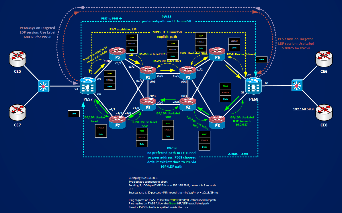
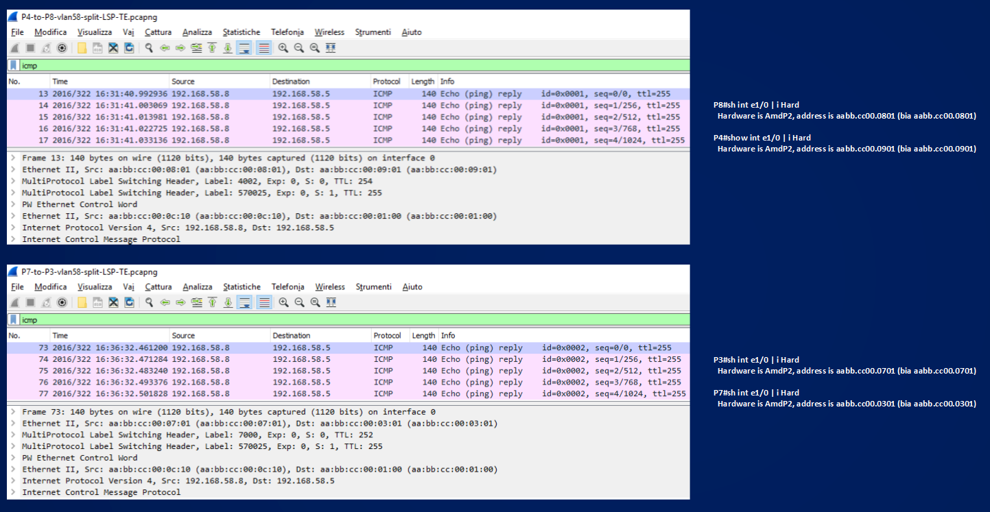
Here you can see the icmp packets packets replies (return traffic) that flow through the IGP/LDP path, you can see the interface MACs of routers so it’s easy to check who sends what.
To recap the scenario:
– Pseudowire58 transports traffic between CE5 and CE8 for VLAN58 between two remote CEs.
– PW58 should follow a predetermined path inside the core
– Configured an MPLS TE Tunnel58 establishing an RSVP/TE LSP from PE57 to PE68
– PW58 will use a pw-class that uses the created interface Tunnel58
With this 4 steps I cannot know what happens to the return traffic coming back from PE68 toward PE57. If I want a symmetric traffic scenario, that is, also the traffic coming back from PE68 to PE57 must follow the same physical path inside the core, one possibility I have is to configure an MPLS/TE Tunnel on PE68 with an Explicit Path that has the same routers in the opposite direction and configure Pseudowire58 to use this MPLS/TE Tunnel:
1000v-PE68#show run | s explicit
ip explicit-path name PW58 enable
next-address 99.0.0.68
next-address 10.0.0.69
next-address 10.0.0.54
next-address 10.0.0.41
next-address 10.0.0.26
next-address 10.0.0.13
next-address 99.0.0.57
1000v-PE68#sh run int Tu58 | b interface
interface Tunnel58
description Tunnel-x-PW58
ip unnumbered Loopback0
tunnel mode mpls traffic-eng
tunnel destination 99.0.0.57
tunnel mpls traffic-eng autoroute announce
tunnel mpls traffic-eng priority 7 7
tunnel mpls traffic-eng bandwidth 100
tunnel mpls traffic-eng path-option 5 explicit name PW58
tunnel mpls traffic-eng path-option 10 dynamic
1000v-PE68#show mpls traffic-engineering tunnels role head | i Tunnel|ath|Label|10\.0|99\.0
Name: Tunnel-x-PW58 (Tunnel58) Destination: 99.0.0.57
Admin: up Oper: up Path: valid Signalling: connected
path option 5, type explicit PW58 (Basis for Setup, path weight 41)
path option 10, type dynamic
Active Path Option Parameters:
State: explicit path option 5 is active
InLabel : –
OutLabel : GigabitEthernet2, 6024
Next Hop : 10.0.0.69
Src 99.0.0.68, Dst 99.0.0.57, Tun_Id 58, Tun_Instance 1
RSVP Path Info:
My Address: 10.0.0.70
Explicit Route: 10.0.0.69 10.0.0.53 10.0.0.54 10.0.0.42
10.0.0.41 10.0.0.25 10.0.0.26 10.0.0.14
10.0.0.13 99.0.0.57
Tunnel:
Time since path change: 1 minutes, 55 seconds
1000v-PE68(config)#pseudowire-class PW58
1000v-PE68(config-pw-class)#preferred-path interface Tu58
1000v-PE68#sh run int g1.58 | b interface
interface GigabitEthernet1.58
encapsulation dot1Q 58
xconnect 99.0.0.57 58 encapsulation mpls pw-class PW58
1000v-PE68#show mpls forwarding-table 99.0.0.57 detail
Local Outgoing Prefix Bytes Label Outgoing Next Hop
Label Label or Tunnel Id Switched interface
680018 Pop Label 99.0.0.57/32 0 Tu58 point2point
MAC/Encaps=14/18, MRU=1500, Label Stack{6024}, via Gi2
AABBCC00060108002717CFE08847 01788000
No output feature configured
Now I have a symmetric traffic condition direct and return traffic for PW58 follow the same path back and forth inside the core.
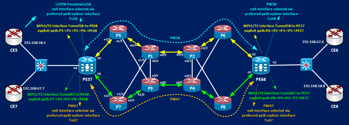
If now, I want to add a second Pseudowire67 and load-share inside the core between the PEs, it’s enough to establish another pair of MPLS/TE Tunnels, Tunnel67 for examples, and configure the pseudowire on both PEs to use a pw-class with an interface options that targets the Tunnel Interfaces. Following pictures recap this scenario.
To summarize Pseudowires Load Sharing scenarios:
– There are two levels of traffic splitting when considering traffic flowing on L2VPN Pseudowires
– First level of splitting it’s about how PEs distributes PWs on their exit interfaces to the P core (inter-PW traffic splitting)
– When multiple PWs are configured on a PEs and Equal Cost Multipaths to the peer address exist, PEs distributes equally the PWs among their interfaces.
– Second level of traffic splitting can be inside the P core within a Pseudowire (intra-PW traffic splitting)
– Traffic in one direction follow always the same LSP path (during normal operations)
– But by default direct traffic from PEx to PEy can follow an LSP path different from the one followed by the return traffic from PEy to PEx.
– Possible asymmetric traffic can be present for the same Pseudowire.
– This asymmetric condition is not specific to Pseudowires but can affect any MPLS application.
– To control the First Level of traffic splitting, an available tool is the “preferred-path” option
– Preferred-path can point to a second peer address (different from the one that signals the pseudowire into the xconnect command)
– The exit interface can be selected by preferred-path modifying the default IGP behavior to have this second peer address reachable through the desired PE’s interface.
– Or preferred-path can be controlled using MPLS/TE traffic-engineering and setting the created MPLS/TE Tunnel interface as parameter of the preferred-path option.
– To use an MPLS/TE Tunnel as parameter of the preferred-path option within a pseudowire-class, TE Tunnels must start and end at PEs where pseudowires are configured.
– Modifying IGP behavior is not scalable and complex from an operational point of view.
– MPLS/TE can be built dynamically or manually using explicit paths.
– Using explicit paths for MPLS/TE I can control also the splitting of the Pseudowire traffic inside the core.
– To have symmetric traffic flow for a Pseudowire using MPLS/TE explicit path steps are:
— Build TWO MPLS/TE Tunnels, one for each PE and for each direction, over opposite explicit paths traversing the same P routers.
— Configure the Pseudowire on both PEs to use a pw-class that uses a preferred-path option with the created MPLS/TE Tunnel interfaces as parameters.
REFERENCE: Layer 2 VPN Architectures