In the previous post “IS-IS Protocol Review” I learned how IS-IS forms adjacency on LAN broadcast and on point-to-point circuits. You can see below the small topology I used. Here I want to understand how is-is routers exchange information about their databases and how these database are built.
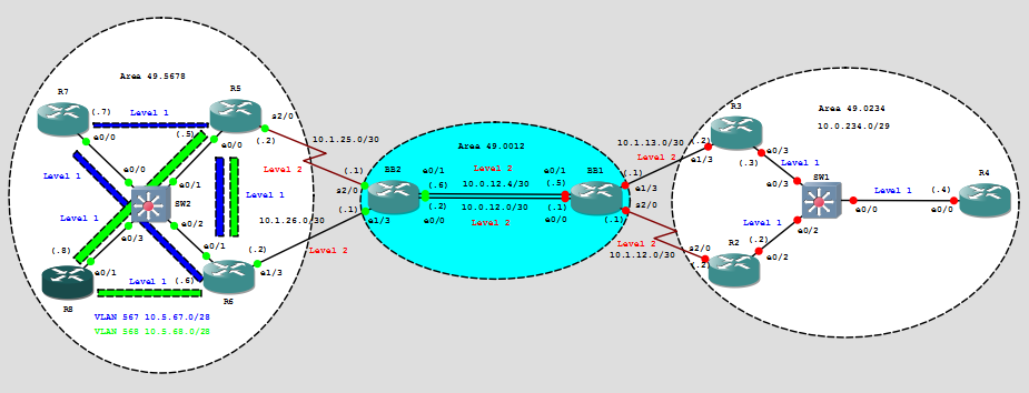
IS-IS is configured on all the router, you can download the zip configuration file here. I’ve kept only interfaces connecting BB1 and BB2 in shut, while activating the links I will capture traffic to inspect IS-IS exchanged info. Below you can see the database created by BB1 and BB2 before activating their connecting links.
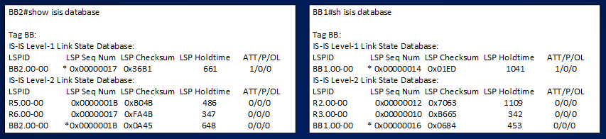
Since BB1s and BB2 are not speaking IS-IS between each other, they have different view of the network, BB1 sees the right side and BB2 sees the left side. The single elements that compose the databases are Link State Protocol Data Unit (LSPs) describing each router in both L1 and L2 databases. Note that neither BB2 nor BB1 have L1 links (see topology above and attached config) but however both routers describes themselves in L1 database, this is due to how IS-IS is implemented in IOS. When activating links between BB1 and BB2 what happens is that both devices exchange this pieces of information.
The single elements are:
BB2:
IS-IS Level-2 Link State Database:
LSPID LSP Seq Num LSP Checksum LSP Holdtime ATT/P/OL
R5.00-00 0x0000001B 0xB04B 486 0/0/0
R6.00-00 0x00000017 0xFA4B 347 0/0/0
BB2.00-00 * 0x0000001B 0x0A45 648 0/0/0
BB1:
IS-IS Level-2 Link State Database:
LSPID LSP Seq Num LSP Checksum LSP Holdtime ATT/P/OL
R2.00-00 0x00000012 0x7063 1109 0/0/0
R3.00-00 0x00000010 0xB665 342 0/0/0
BB1.00-00 * 0x00000016 0x0684 453 0/0/0
Note that there is no Pseudo-Node describing the LAN circuit connecting BB2 to R6 and BB1 to R3, this is because I configured the LAN circuit as point-to-point is-is network, just to recap here the configuration of e1/3 ports on BB routers:
BB2#sh run interface e1/3 | b interface
interface Ethernet1/3
mac-address 0002.0000.0013
ip address 10.1.26.1 255.255.255.252
ip router isis BB
isis circuit-type level-2-only
isis network point-to-point
isis three-way-handshake ietf
BB1#sh run int e1/3 | b interface
interface Ethernet1/3
mac-address 0001.0000.0013
ip address 10.1.13.1 255.255.255.252
ip router isis BB
isis circuit-type level-2-only
isis network point-to-point
isis three-way-handshake ietf
Looking at a detailed show about one element:
BB2#show isis database verbose R6.00-00
Tag BB:
IS-IS Level-2 LSP R6.00-00
LSPID LSP Seq Num LSP Checksum LSP Holdtime ATT/P/OL
R6.00-00 0x0000001B 0xF24F 1189 0/0/0
Area Address: 49.5678 ==> TLV#1
NLPID: 0xCC ==> TLV#129
Hostname: R6 ==> TLV#137
IP Address: 6.6.6.6 TLV#134
Metric: 10 IP 10.1.26.0 255.255.255.252 ==> TLV#128
Metric: 10 IS BB2.00 ==> TLV#2
Metric: 10 IP 5.5.5.5 255.255.255.255 ==> TLV#128
Metric: 0 IP 6.6.6.6 255.255.255.255 ==> TLV#128
Metric: 10 IP 7.7.7.7 255.255.255.255 ==> TLV#128
Metric: 10 IP 8.8.8.8 255.255.255.255 ==> TLV#128
Metric: 10 IP 10.5.67.0 255.255.255.240 ==> TLV#128
Metric: 10 IP 10.5.68.0 255.255.255.240 ==> TLV#128
BB1#sh isis database verbose R3.00-00
Tag BB:
IS-IS Level-2 LSP R3.00-00
LSPID LSP Seq Num LSP Checksum LSP Holdtime ATT/P/OL
R3.00-00 0x00000013 0xB068 517 0/0/0
Area Address: 49.0234
NLPID: 0xCC
Hostname: R3
IP Address: 3.3.3.3
Metric: 10 IP 10.1.13.0 255.255.255.252
Metric: 10 IS BB1.00
Metric: 10 IP 2.2.2.2 255.255.255.255
Metric: 0 IP 3.3.3.3 255.255.255.255
Metric: 10 IP 4.4.4.4 255.255.255.255
Metric: 10 IP 10.0.234.0 255.255.255.248
Every element in the database describes some information that will be encoded in specific TLVs when Link State PDU (LSP) will be exchanged.
Now, I’m going to activate the first link (e0/0) between BB2 and BB1 and capture the packets, here the configuration of the interfaces:
BB2#
interface Ethernet0/0
mac-address 0002.0000.0000
ip address 10.0.12.2 255.255.255.252
ip router isis BB
shutdown
isis circuit-type level-2-only
isis network point-to-point
isis three-way-handshake ietf
BB1#
interface Ethernet0/0
mac-address 0001.0000.0000
ip address 10.0.12.1 255.255.255.252
ip router isis BB
shutdown
isis circuit-type level-2-only
isis network point-to-point
isis three-way-handshake ietf
BB2(config)#int e0/0
BB2(config-if)#no shut
*Jul 7 16:03:58.920: %LINK-3-UPDOWN: Interface Ethernet0/0, changed state to up
*Jul 7 16:03:59.928: %LINEPROTO-5-UPDOWN: Line protocol on Interface Ethernet0/0, changed state to up
BB1(config)#int e0/0
BB1(config-if)#no shut
*Jul 7 16:04:14.097: %LINK-3-UPDOWN: Interface Ethernet0/0, changed state to up
*Jul 7 16:04:15.099: %LINEPROTO-5-UPDOWN: Line protocol on Interface Ethernet0/0, changed state to up
Below you can see the captured packets:
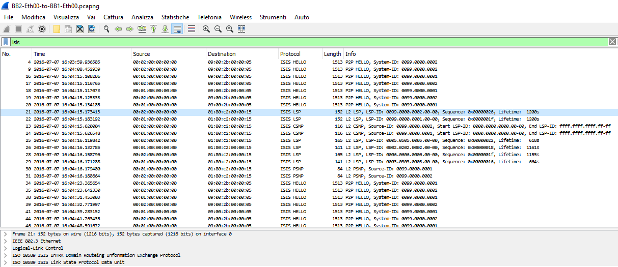
Reading the capture I can see that BB2 and BB1 using ten messages are able to exchange their database info, these messages are of 3 types:
1] Link State Protocol Data Unit (LSP)
2] Complete Sequence Number Protocol Data Unit (CSNP)
3] Partial Sequence Number Protocol Data Unit (PSNP)
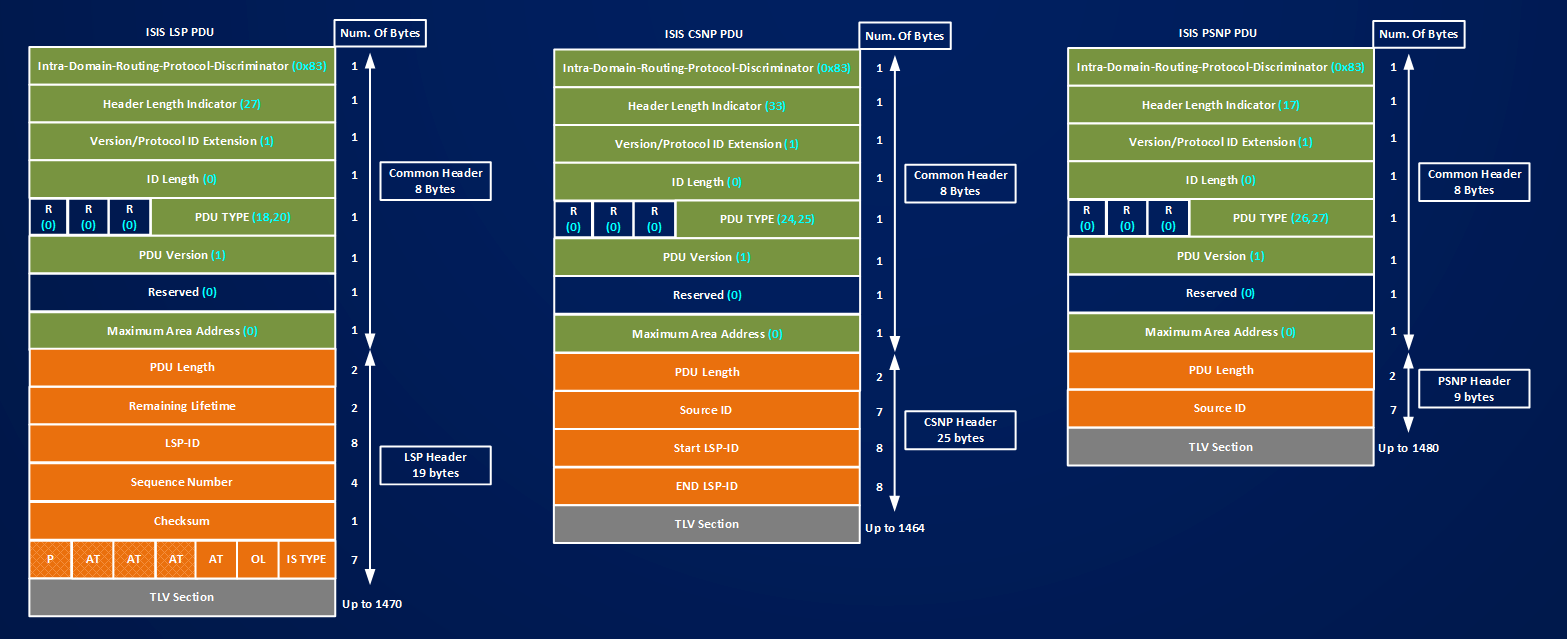
After becoming adjacent the two IS-IS speaking routers start to exchange database information, the first packet of this type that can be seen in the capture is a LSP PDU sent by BB2 toward BB1 (frame 21), in the above picture you have the general structure of an LSP, let’s see how this PDUs are built in detail by both routers
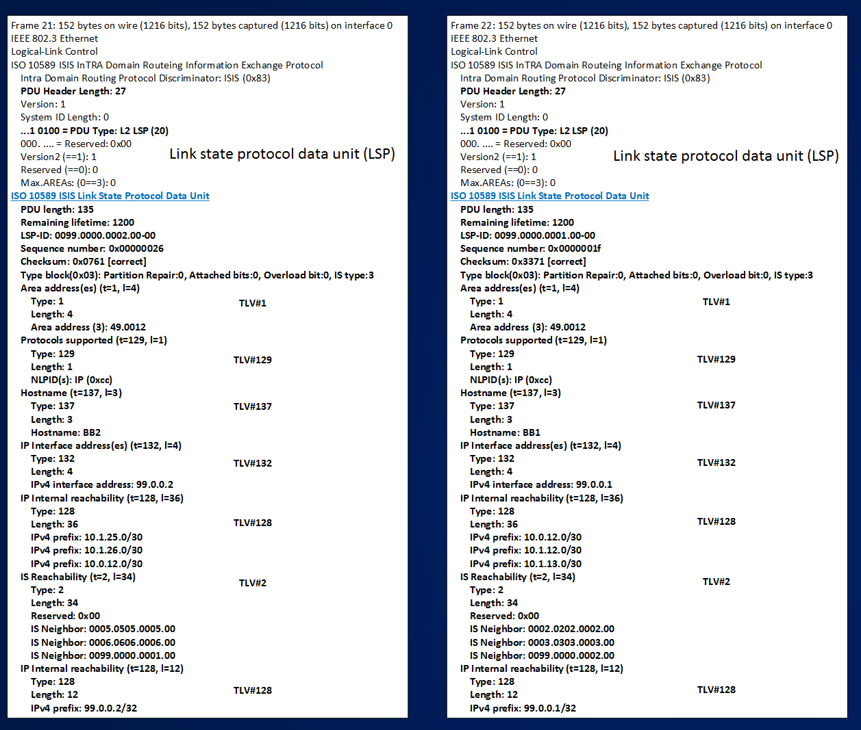
I see that first thing both routers do is to send information about themselves encoded in an LSP, looking at the LSP sent by BB2:
a] A common IS-IS Header (8 bytes)
b] LSP Header (19 bytes):
==> PDU Length (this is the length of the entire PDU including the common header, LSP header, and the payload, in this case 135 byte)
==> Remaining Life Time (in this case value is 1200 (deafult value) LSP just created)
==> LSP-ID (this is the identifier of the entry in the database, in this case 0099.0000.0002.00-00)
==> Sequence Number (looking at this routers know if an LSP is newer than another one, value is 0x00000026)
==> Type Block (info about overload bit, attach bit, see previous section for more details)
c] After the LSP Header, BB2 encodes in different TLVs some information about itself, specifically I can see:
TLV#1 ==> Area Address = 49.0012
TLV#129 ==> Supported Protocols = IP (0xcc)
TLV#137 ==> Hostname = BB2
TLV#132 ==> IP interface Address (99.0.0.2)
A note about TLV132#: In the previous section I saw that TLV#132 (like others TLVs) can be used in different IS-IS messages, specifically I saw that it is used in HELLO PDUs, when used in Hello Packets TLV#132 encodes the IP address of the interface that is used to send the packet, this information is used for common subnet checking and to avoid duplication of IP addresses on different routers; here I can see that the encoded IP Address is different from the one used in Hello Packets. Here IP Address is 99.0.0.2, that is the address configured on the Loopback interface. I didn’t find any specific information about this, I suppose that this is implementation-dependent (both IOS and Junos use a router-id-like logic in LSP PDU for IP address used on TLV#132)
TLV#128 ==> IP Internal Reachability
This TLV describes the local connected IP prefixes, each IP is described by 12 bytes
IP Internal reachability (t=128, l=36)
Type: 128
Length: 36
IPv4 prefix: 10.1.25.0/30
IPv4 prefix: 10.1.26.0/30
IPv4 prefix: 10.0.12.0/30
IPv4 prefix: 10.1.25.0/30
..11 0010 = Default Metric: 50
.0.. …. = Default Metric IE: Internal
0… …. = Distribution: Down
..00 0000 = Delay Metric: 0
1… …. = Delay Metric: Not Supported
.0.. …. = Delay Metric: Internal
..00 0000 = Expense Metric: 0
1… …. = Expense Metric: Not Supported
.0.. …. = Expense Metric: Internal
..00 0000 = Error Metric: 0
1… …. = Error Metric: Not Supported
.0.. …. = Error Metric: Internal
The 12 bytes bring information about the metric value and the metric Type (internal/external) for each of the four topology written in the specification (but today only the default metric is used).
TLV#2 ==> IS Reachability
This TLV describes the list of neighbors only from a topological point of view (no IP info)
IS Reachability (t=2, l=34)
Type: 2
Length: 34
Reserved: 0x00
IS Neighbor: 0005.0505.0005.00
IS Neighbor: 0006.0606.0006.00
IS Neighbor: 0099.0000.0001.00
each neighbor is described by a multidimensional metric but, again, only default metric is supported:
IS Neighbor: 0005.0505.0005.00
..11 0010 = Default Metric: 50
.0.. …. = Default Metric: Internal
..11 0010 = Delay Metric: 50
0… …. = Delay Metric: Supported
.0.. …. = Delay Metric: Internal
..11 0010 = Expense Metric: 50
0… …. = Expense Metric: Supported
.0.. …. = Expense Metric: Internal
..11 0010 = Error Metric: 50
0… …. = Error Metric: Supported
.0.. …. = Error Metric: Internal
IS Neighbor: 0005.0505.0005.00
After this first exchange of LSPs BB1 learns a description of BB2 (its name, its directly IP addresses, other neighbors connected to BB2), the same happens for BB2 the other way around.
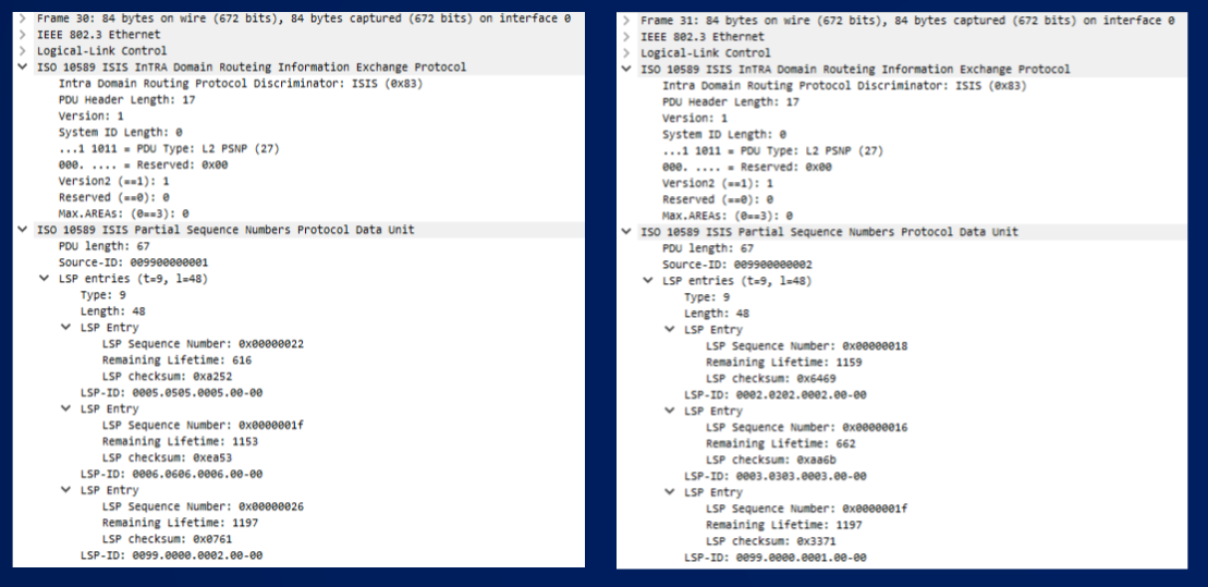
Let’s move down on the captured packets, after these first two LSPs, routers exchange two CSNP packets. Below you can see the details about these PDUs.
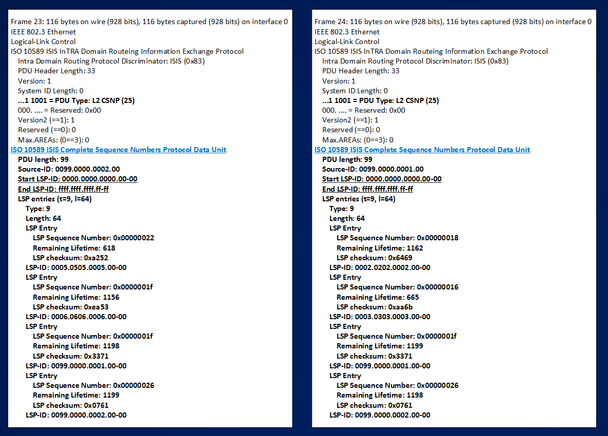
After the common IS-IS header, the CSNP header describes:
==> PDU Length (this is the length of the entire PDU including the common header, CSNP header, and the payload, in this case 99 bytes)
==> Source-ID (the System-ID of the device originating the PDU)
Then we have, two fields that are the core of the meaning of the CSNP PDU. These Two fields are:
==> Start LSP-ID
==> End LSP-ID
Sending these two fields the IS-IS speaking router informs the neighbor about the LSP-IDs contained in its database, CSNPs can be considered a description of the entire database built by a router. These two fields may have special value when the description of the entire database can be contained in a single CSNP. These special value are:
Start LSP-ID = 0000.0000.0000.00-00
End LSP-ID = ffff.ffff.ffff.ff-ff
When a routers sends these value is saying “following is the list of all LSP-IDs I have in my database for this level (1 or 2 based on the type of CSNP 24 or 25)”
Every good book about IS-IS, like this one , does some math about how many LSP-IDs a router can pack in a CSNP.
To understand this math computation look at how each LSP-ID is encoded in a CSNP packet, after Start and End LSP-ID a special TLV#9 “LSP-Entries” begins, the general structure of this TLV can be reviewed here:
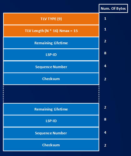
==> TLV Type = 9
==> TLV Length = N * 16, since the field is 1 byte, the maximum value I can express is 255, each TLV entry is a structure of 16 bytes (Remaining Lifetime, LSP-ID, Sequence Number and Checksum), then N can be max up to 15, 15 x 16 = 240 bytes.
In my example I see BB2 advertise 4 LSP Entries for (16×4) 64 bytes of information
LSP entries (t=9, l=64)
Type: 9
Length: 64
LSP Entry
LSP Sequence Number: 0x00000022
Remaining Lifetime: 618
LSP checksum: 0xa252
LSP-ID: 0005.0505.0005.00-00
LSP Entry
LSP Sequence Number: 0x0000001f
Remaining Lifetime: 1156
LSP checksum: 0xea53
LSP-ID: 0006.0606.0006.00-00
LSP Entry
LSP Sequence Number: 0x0000001f
Remaining Lifetime: 1198
LSP checksum: 0x3371
LSP-ID: 0099.0000.0001.00-00
LSP Entry
LSP Sequence Number: 0x00000026
Remaining Lifetime: 1199
LSP checksum: 0x0761
LSP-ID: 0099.0000.0002.00-00
Similar thing does BB1:
LSP entries (t=9, l=64)
Type: 9
Length: 64
LSP Entry
LSP Sequence Number: 0x00000018
Remaining Lifetime: 1162
LSP checksum: 0x6469
LSP-ID: 0002.0202.0002.00-00
LSP Entry
LSP Sequence Number: 0x00000016
Remaining Lifetime: 665
LSP checksum: 0xaa6b
LSP-ID: 0003.0303.0003.00-00
LSP Entry
LSP Sequence Number: 0x0000001f
Remaining Lifetime: 1199
LSP checksum: 0x3371
LSP-ID: 0099.0000.0001.00-00
LSP Entry
LSP Sequence Number: 0x00000026
Remaining Lifetime: 1198
LSP checksum: 0x0761
LSP-ID: 0099.0000.0002.00-00
Coming back to some math, the IS-IS message CSNP has 33 bytes of Header information (8 bytes for common header, 25 bytes for CSNP header), this means that we have 1497 – 33 = 1464 bytes to fit with LSP Entries information, we must add 2 bytes of overhead for each TLV#9, then the biggest TLV#9 we can form will be of 242 bytes ==> the maximum number of maximum-size TLV#9 we can put in a CSNP packet is 1464/242=6,049586776859504 = 6, since in each TLV#9 of 242 bytes we have 15 LSP-ID (see above) ==> the maximum number of LSP-IDs we can put in a CSNP packets is 15*6 = 90
Then, if the database of the routers has up to 90 LSP-IDs, the entire database can be described by a single CSNP. In my example we are quite under this 90 limit, then both routers send only one CSNP to each other. If a routers has a database containing more than 90 LSP-IDs, it must build more than one CSNP, for example let’s suppose a routers has 200 LSP-IDs, it must build 3 CSNPs, in the header of these 3 CSNP the Start and End LSP-ID will be:
First CSNP ==> Start LSP-ID = 0000.0000.0000.00-00 | End LSP-ID = xxxx.xxxx.xxxx.xx-xx (the 90th LSP-ID)
Second CSNP ==> Start LSP-ID = yyyy.yyyy.yyyy.yy-yy (the 91th LSP-ID) | End LSP-ID = zzzz.zzzz.zzzz.zz-zz (the 180th LSP-ID)
Third CSNP ==> Start LSP-ID = qqqq.qqqq.qqqq.qq-qq (the 181th LSP-ID) | End LSP-ID = ffff.ffff.ffff.ff-ff (the 200th LSP-ID)
Now, how routers use this information contained in the CSNP packets? When a router receives the CSNP, it can compare the database description of its neighbor with its own database, for example consider BB2, BB2 has at the beginning these LSP-ID in its Level-2 database:
LSP-ID: 0005.0505.0005.00-00 (R5)
LSP-ID: 0006.0606.0006.00-00 (R6)
LSP-ID: 0099.0000.0001.00-00 (BB1)
LSP-ID: 0099.0000.0002.00-00 (BB2 – itself)
when it receives CSNP from BB1 it reads in this packet:
LSP-ID: 0002.0202.0002.00-00 (R2)
LSP-ID: 0003.0303.0003.00-00 (R3)
LSP-ID: 0099.0000.0001.00-00 (BB1)
LSP-ID: 0099.0000.0002.00-00 (BB2)
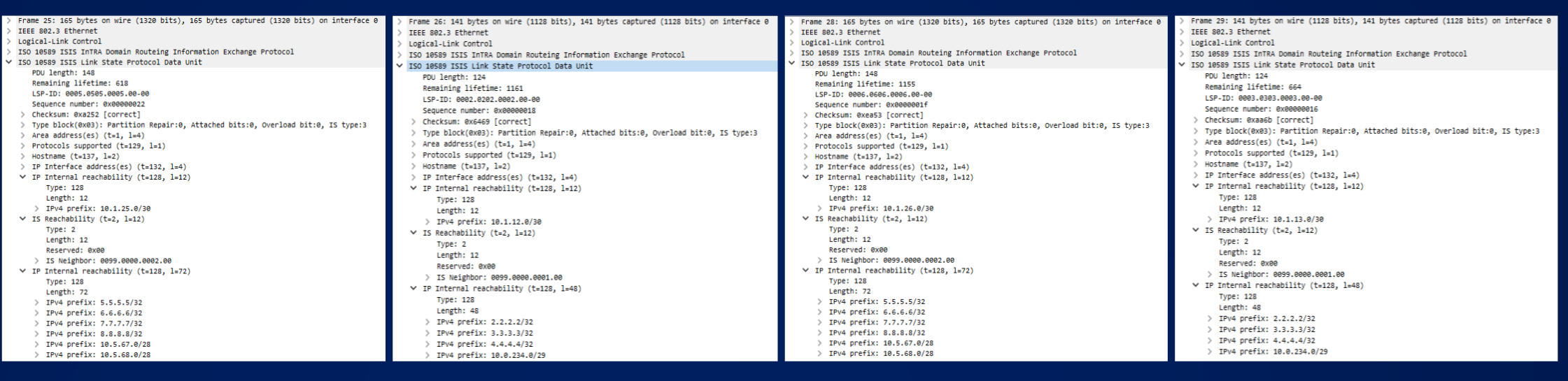
Comparing the LSP-IDs, if finds that BB1 is not aware of the existence of R5 and R6 (LSP-IDs of these routers are missing in the CSNP sent by BB1), the same thing does BB1 when receiving the CSNP from BB2, BB1 finds that BB2 is not aware of R2 and R3, LSP-IDs are missing in the CSNP packet sent by BB2. What the routers do is update the neighbors with the missing information, result of this is that BB2 immediately send two new LSPs describing R5 and R6 to BB1 and BB1 sends two LSPs describing R2 and R3 to BB2. The corresponding frames in the capture are in alternate sequence (BB2, BB1, BB2, BB1) 25,26,28,29, below you can find a partial view of the 4 LSPs:
Moving down the wireshark capture, I see that to conclude the database exchange BB1 and BB2 send to each other one further packet, this packet is a PSNP PDU, above you can check the general structure of this PDU, below you can see this packet in detail:
I can see that PSNP uses TLV#9 to describe some entries, but what are these PSNPs used for?
I can see that BB1 lists these entries in its PSNP:
LSP-ID: 0005.0505.0005.00-00
LSP-ID: 0006.0606.0006.00-00
LSP-ID: 0099.0000.0002.00-00
and that BB2 lists these entries in its PSNP:
LSP-ID: 0002.0202.0002.00-00
LSP-ID: 0003.0303.0003.00-00
LSP-ID: 0099.0000.0001.00-00
PSNPs are used by each router to acknowledge the receipt of each single LSPs sent by the neighbor. For example BB1 acknowledges LSP-IDs describing R5,R6 and BB2 (the first LSP BB2 sent after becoming neighbor of BB1) the same thing has been done by BB2 (it acknowledges R2, R3 and BB1).
Then, to recap the process:
a) BB2 and BB1 becomes neighbors.
b) Routers send to each other a Full LSP describing themselves to the discovered neighbor.
c) Each router sends a complete description of the content of its database (CSNP packets).
d) Each router compares the received description and send Full LSPs about the LSP-IDs that are missing from the database of the neighbor.
e) Each router acknowledges every received LSPs using PSNP packets listing all the received LSPs.
Note that the described process runs over point-to-point isis network, though the links are of broadcast type, I’ve configured the command “isis network point-to-point” under the interfaces connecting BB2 to BB1.
What does change in the described process if the links are true broadcast links and then a Pseudo-Node describing the LAN is present in the network? Let’s see.
Let’s consider the right side of the network, to test how routers exchange info on a broadcast circuit I will shut the LAN segment and then I will reactivate links between R2,R3 and R4 capturing the packets.
I chose R3 as Designated Intermediate Systems (DIS) on the LAN, setting its priority to the maximum possible value, that is 127:
interface Ethernet0/3
mac-address 0000.0003.0003
ip address 10.0.234.3 255.255.255.248
ip router isis RIGHT
isis circuit-type level-1
isis priority 127
After shutting down the links on the broadcast segment between R2,R3 and R4, IS-IS databases of these routers are:
R3#show isis database
Tag RIGHT:
IS-IS Level-1 Link State Database:
LSPID LSP Seq Num LSP Checksum LSP Holdtime ATT/P/OL
R3.00-00 * 0x00000003 0x7AD1 1120 1/0/0
IS-IS Level-2 Link State Database:
LSPID LSP Seq Num LSP Checksum LSP Holdtime ATT/P/OL
R2.00-00 0x00000003 0x5261 1114 0/0/0
R3.00-00 * 0x00000003 0xEF06 1116 0/0/0
R5.00-00 0x00000004 0xDE34 1142 0/0/0
R6.00-00 0x00000004 0x2138 1142 0/0/0
BB1.00-00 0x00000004 0x3F80 1115 0/0/0
BB2.00-00 0x00000005 0x5E2B 1113 0/0/0
R2#show isis database
Tag RIGHT:
IS-IS Level-1 Link State Database:
LSPID LSP Seq Num LSP Checksum LSP Holdtime ATT/P/OL
R2.00-00 * 0x00000003 0xD880 1096 1/0/0
IS-IS Level-2 Link State Database:
LSPID LSP Seq Num LSP Checksum LSP Holdtime ATT/P/OL
R2.00-00 * 0x00000003 0x5261 1092 0/0/0
R3.00-00 0x00000003 0xEF06 1088 0/0/0
R5.00-00 0x00000004 0xDE34 1117 0/0/0
R6.00-00 0x00000004 0x2138 1117 0/0/0
BB1.00-00 0x00000004 0x3F80 1091 0/0/0
BB2.00-00 0x00000005 0x5E2B 1088 0/0/0
R4#show isis database
Tag RIGHT:
IS-IS Level-1 Link State Database:
LSPID LSP Seq Num LSP Checksum LSP Holdtime ATT/P/OL
R4.00-00 * 0x00000002 0x1632 1091 0/0/0
IS-IS Level-2 Link State Database:
LSPID LSP Seq Num LSP Checksum LSP Holdtime ATT/P/OL
R4.00-00 * 0x00000002 0x4602 1091 0/0/0
What I’m interested in now is the Level-1 database, at the moment all routers have only themselves in this database because links to the switch SW1 are in shut.
I’m going to activate links in this order and capturing packets:
R3’s e0/3
R2’s e0/2
R4’s e0/0
R3(config)#int e0/3
R3(config-if)#no shut
*Aug 1 16:42:12:556: %LINK-3-UPDOWN: Interface Ethernet0/3, changed state to up
*Aug 1 16:42:13:562: %LINEPROTO-5-UPDOWN: Line protocol on Interface Ethernet0/3, changed state to up
After activating interface e0/3, R3 starts to send Hello PDUs on the LAN segment:
R3#
*Aug 1 16:42:13.571: ISIS-Adj: Sending L1 LAN IIH on Ethernet0/3, length 1497
*Aug 1 16:42:22.991: ISIS-Adj: Sending L1 LAN IIH on Ethernet0/3, length 1497
*Aug 1 16:42:30.516: ISIS-Adj: Sending L1 LAN IIH on Ethernet0/3, length 1497
R2(config)#int e0/2
R2(config-if)#no shut
*Aug 1 16:43:06:832: %LINK-3-UPDOWN: Interface Ethernet0/2, changed state to up
*Aug 1 16:43:07:838: %LINEPROTO-5-UPDOWN: Line protocol on Interface Ethernet0/2, changed state to up
R2 starts to send Hello PDUs too, both routers exchange Hello PDU claiming to be the DIS:
R3#
*Aug 1 16:43:07.839: ISIS-Adj: Rec L1 IIH from 0000.0002.0002 (Ethernet0/3), cir type L1, cir id 0002.0202.0002.01, length 1497, ht(30)
*Aug 1 16:43:07.839: ISIS-Adj: New adjacency, level 1 for 0000.0002.0002
*Aug 1 16:43:07.847: ISIS-Adj: Sending L1 LAN IIH on Ethernet0/3, length 1497
R2#
*Aug 1 16:43:07.839: ISIS-Adj: Sending L1 LAN IIH on Ethernet0/2, length 1497
*Aug 1 16:43:07.848: ISIS-Adj: Rec L1 IIH from 0000.0003.0003 (Ethernet0/2), cir type L1, cir id 0003.0303.0003.01, length 1497, ht(30)
*Aug 1 16:43:07.848: ISIS-Adj: New adjacency, level 1 for 0000.0003.0003
After some time, DIS election starts and at the end of this process R3 will win due to best priority (127)
R3#
*Aug 1 16:43:08.844: ISIS-Adj: Run level-1 DR election for Ethernet0/3
*Aug 1 16:43:08.844: ISIS-Adj: New level-1 DR 0003.0303.0003 on Ethernet0/3
*Aug 1 16:43:09.848: ISIS-Adj: Rec L1 IIH from 0000.0002.0002 (Ethernet0/3), cir type L1, cir id 0003.0303.0003.01, length 1497, ht(30)
R2#
*Aug 1 16:43:08.848: ISIS-Adj: Run level-1 DR election for Ethernet0/2
*Aug 1 16:43:08.848: ISIS-Adj: New level-1 DR 0003.0303.0003 on Ethernet0/2
NOTE: Looking at the cir id value in the debug message it’s possible to check which system each router thinks to be the DIS.
After the DIS election ends, looking at the capture (see below the four frames 71,72,73,75), I can see that both R3 and R2 sends an LSP packet (frame 72 and 73) describing themselves to the other router:

Here you can see an expanded view of the 2 LSPs:
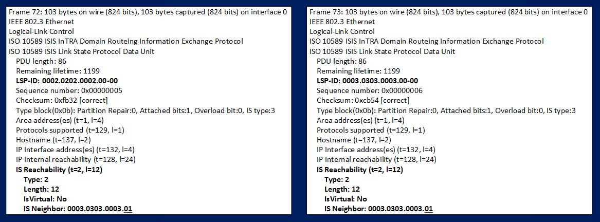
Looking at the LSPs I can see that both routers claims to be connected to a neighbor (look at the Neighbor info reported in TLV#2 IS Reachability listed in the packets) identified by this NODE-ID (System-ID + Pseudo-Node-ID) 0003.0303.0003.01 that is the DIS elected on the segment and whose role is played by router R3.
Looking at the next picture it’s possible to see how R3, playing the role of the DIS router, sends an LSP describing the pseudo-node router on the LAN (frame 76):
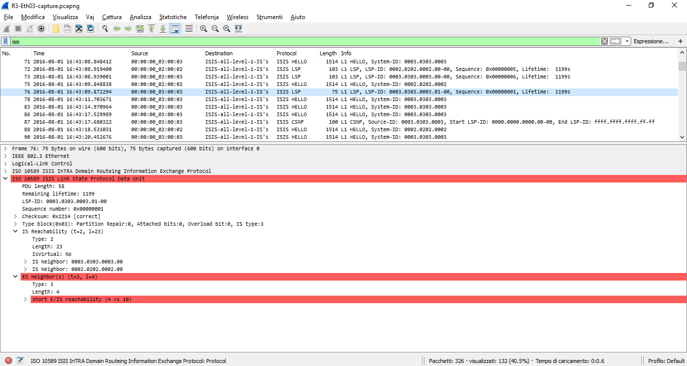
You see that LSP-ID is 0003.0303.0003.01-00 and that in the TLV#2 IS Reachability reported neighbors are 0003.0303.0003.00 (that is R3) and 0002.0202.0002.00 (that is R2)
#################### NOTE ##########################
With the version of wireshark I’m using (2.0.2) you can see that there is an error in decoding the LSP packet describing the Pseudo-Node. The malformed portion of the packet comes from this section of IS-IS ISO specification:
§§§§§§§§§§§§§§§§§§§§§§§§§§§§§§§§§§§§§§§§§§§§§§§§§§§§
3.1.3. ES Neighbors TLV
ISO/IEC 10589 [ISIS-ISO] section 7.3.7 specifies inserting an ES Neighbor TLV in L1 LSPs, with the system ID of the router. RFC 1195 [ISIS-IP] relieves IP-only routers of this requirement. However, for routers that do insert this ESN TLV in L1 LSPs (whether IP-only or OSI-capable), then in an extended LSP, the ESN TLV should include the relevant Additional system-id. Furthermore, OSI-capable routers should accept packets destined for this Additional system-id.
§§§§§§§§§§§§§§§§§§§§§§§§§§§§§§§§§§§§§§§§§§§§§§§§§§§§
Now, for what I’m discussing here this portion of the packet is not so important, maybe that wireshark cannot decode it in the right way or the packet is malformed, anyway I tried to enable IS-IS level-2 on the links forming the LAN segment and in this case (how ISO specification rules) the ES Neighbors TLV is not created), then for the rest of this discussion, simply, we can disregard this portion of the L1 LSP describing the pseudo node.
################# END NOTE #########################
Let’s move down on the wireshark capture (here you can download the three files containing the full capture for the three interface of R3,R2,R4). After the DIS is elected on the LAN, only the DIS is responsible to keep the IS-IS database info updated and periodically it sends a CSNP PDU describing its entire database, if the LAN segment is stable routers that are not-DIS simply listen to the periodic info sent by the DIS router.
R3#
*Aug 1 16:43:17.680: ISIS-SNP: Sending L1 standard CSNP on Ethernet0/3
*Aug 1 16:43:25.677: ISIS-SNP: Sending L1 standard CSNP on Ethernet0/3
*Aug 1 16:43:34.065: ISIS-SNP: Sending L1 standard CSNP on Ethernet0/3
In next picture you can see the periodic CSNP sent by DIS R3:
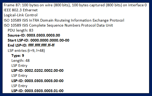
R3 lists in CSNP PDUs, using TLV#9 LSP Entry, all the LSP-ID contained in its database, these are the ones describing R3 itself, R2 and the DIS (0003.0303.0003.01-00)
NOTE: all the 3 LSP-ID are already known to R2 when R3 starts to generate periodic CSNPs, so R2 does nothing because it sees no change.
Let’s see what happens when R4 joins the LAN segment too:
R4(config)#int e0/0
R4(config-if)#no shut
*Aug 1 14:44:57.331: %LINK-3-UPDOWN: Interface Ethernet0/0, changed state to up
*Aug 1 14:44:58.337: %LINEPROTO-5-UPDOWN: Line protocol on Interface Ethernet0/0, changed state to up
R4 start to send Hello PDUs on the LAN segment, R3 receives a new Hello PDU by R4, in this PDUs R4 claims to be the DIS, R3 continues to send its Hello PDUs claiming to be the DIS, a new DIS election start after discovering new neighbors:
R3#
*Aug 1 16:44:58.347: ISIS-Adj: Rec L1 IIH from 0000.0004.0000 (Ethernet0/3), cir type L1, cir id 0004.0404.0004.01, length 1497, ht(30)
*Aug 1 16:44:58.347: ISIS-Adj: New adjacency, level 1 for 0000.0004.0000
*Aug 1 16:44:58.355: ISIS-Adj: Sending L1 LAN IIH on Ethernet0/3, length 1497
*Aug 1 16:44:59:351: %CLNS-5-ADJCHANGE: ISIS: Adjacency to 0004.0404.0004 (Ethernet0/3) Up, new adjacency
*Aug 1 16:44:59.352: ISIS-Adj: Run level-1 DR election for Ethernet0/3
*Aug 1 16:44:59.352: ISIS-Adj: No change (it’s us)
R4:
*Aug 1 16:44:58.356: ISIS-Adj: Rec L1 IIH from 0000.0003.0003 (Ethernet0/0), cir type L1, cir id 0003.0303.0003.01, length 1497, ht(10)
*Aug 1 14:44:59.356: %CLNS-5-ADJCHANGE: ISIS: Adjacency to 0003.0303.0003 (Ethernet0/0) Up, new adjacency
*Aug 1 16:44:59.356: ISIS-Adj: Run level-1 DR election for Ethernet0/0
*Aug 1 16:44:59.356: ISIS-Adj: New level-1 DR 0003.0303.0003 on Ethernet0/0
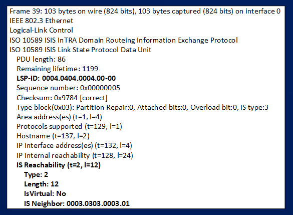
After the DIS election is completed, R4 sends an LSP on the LAN segment describing itself (frame 227 in the file R3-Eth03-capture or frame 39 in the file R4-Eth00-capture), below you can see the expanded LSP:
R3 playing the role of the DIS updates its database and sends an updated version of CSNP:
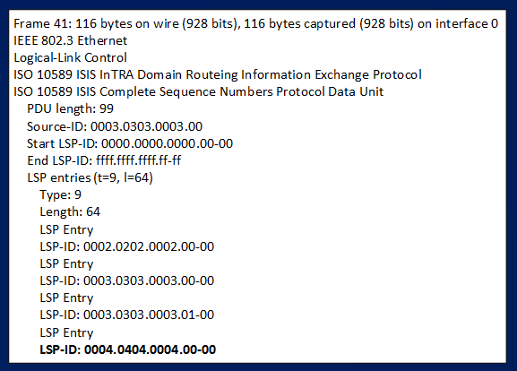
It’s easy to see that now R3 lists the new LSP-ID that describes R4.
Looking at messages generated by R4 we can confirm the receipt of this CSNP PDU:
R4#
*Aug 1 16:45:00.203: ISIS-Snp: Rec L1 CSNP from 0003.0303.0003 (Ethernet0/0)
*Aug 1 16:45:00.203: ISIS-SNP: CSNP range 0000.0000.0000.00-00 to FFFF.FFFF.FFFF.FF-FF
*Aug 1 16:45:00.203: ISIS-SNP: Entry L1 0002.0202.0002.00-00, seq 5 not in LSP database, adding dummy
*Aug 1 16:45:00.203: ISIS-SNP: Entry L1 0003.0303.0003.00-00, seq 6 not in LSP database, adding dummy
*Aug 1 16:45:00.204: ISIS-SNP: Entry L1 0003.0303.0003.01-00, seq 1 not in LSP database, adding dummy
Look how R4 doesn’t know about LSP-ID 0002.0202.0002.00-00, 0003.0303.0003.00-00, 0003.0303.0003.01-00 (DIS) (they are “not in LSP database“, “adding dummy” means “I have no information about those LSPs, I need to install those LSPs in my database but I can do it as soon as I receive full info about them from DIS, then I have to ask DIS to send me full LSPs sending a PSNP that lists these same LSPs”
Now, see below for the next SNP PDUSs exchanged (frame from 41 to 46)
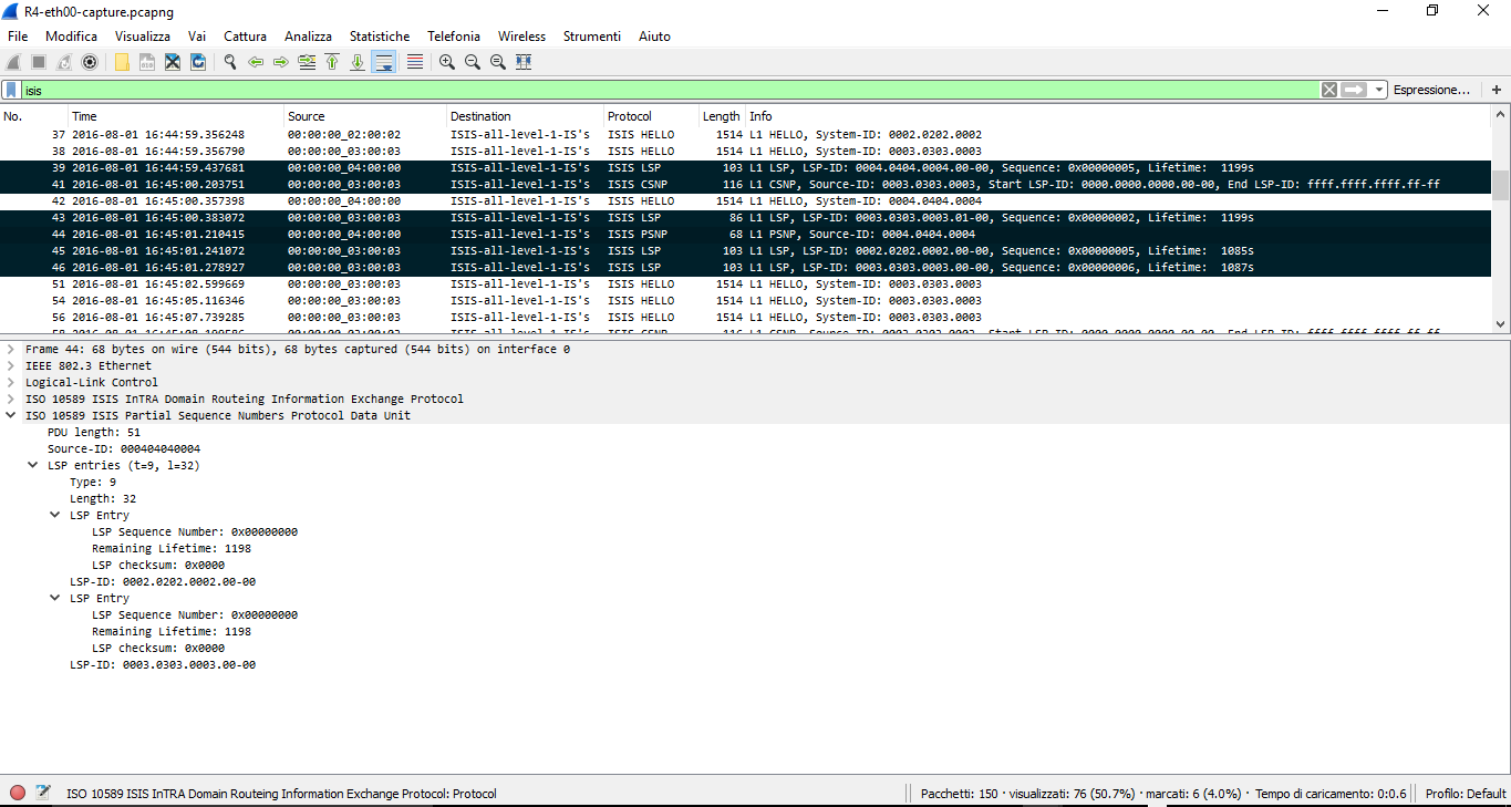
Before R4 builds its PSNP, it receives a new version of LSP-ID 0003.0303.0003.01-00 with Sequence Number = 0x00000002 (R3 sends this LSP because when it received the LSP 0004.0404.0004.00-00 it had to renew LSP 0003.0303.0003.01-00, updating the Sequence Number from 1 to 2, to count the new neighbor on the LAN segment). At this time R4 has already an updated version of LSP 0003.0303.0003.01-00, (it was missing version 1, it received version 2) then the next action performed by R4 is to ask the DIS more detailed info about the two missing LSPs, sending a PSNP PDU (frame 44) listing in TLV#9 the two missing LSPs (0002.0202.0002.00-00, 0003.0303.0003.00-00):
You can see in the above picture the expanded view of the PSNP sent by R4.
It’s interesting to note that the LSP entries are built with Sequence Number = 0x00000000 and Checksum = 0x00000000 in this PSNP, these null(zero) values means that R4 is asking the DIS Router (R3) the reflooding of these 2 LSPs, R3 does this sending the LSPs in frames 45 and 46.
Once R4 has synchronized its database with the one of the DIS Router, the only periodic PDUs are the CSNPs sent by R3. Note that during R3-R4 database synchronization no SNP packet is sent by R2, R2 simply listens to the update version (LSPs or CSNPs) sent by R3 and it updates its database as a consequence.
The overall process on broadcast circuit can be summarized in this way:
a) Routers on LAN segment exchange Hello PDUs and becomes Neighbors.
b) Newly activated routers send an LSP describing themselves.
c) A DIS election starts.
d) The router that becomes DIS is in charge to maintain Database synchronization, it sends periodically CSNPs describing the content of its database.
e) Other not-DIS routers listen to the CSNPs and LSPs sent by the DIS.
f) When not-DIS routers, looking at the received CSNPs, see that some LSP are missing from their database, they build and sends PSNP PDUs listing all the missing LSP-IDs in TLV#9 entries that have Sequence Number and Checksum set to 0x00000000.
g) When the DIS receives these PSNPs, looks at the LSP entries inside the packet and refloods the full LSPs about those missing LSPs.
If you had the patience to read so far, you should now be aware about how IS-IS discovers neighbors, builds adjacencies and an idea about how it synchronizes databases of the connected routers. What happens when the network is stable and a change happens? You can read some notes about that in the next “coming soon” arcticle.