In the following pages I would like to review the IS-IS Routing Protocol, testing some simple topologies that can help me to better memorize its concepts.
Before proceeding with configuring the routers and discuss the topology, here are some useful reference to learn about IS-IS routing protocol:
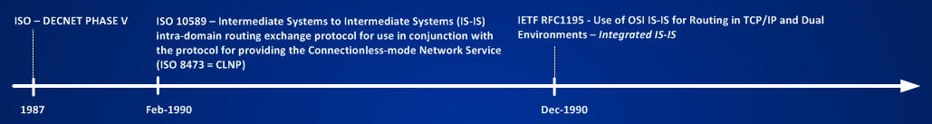
“The Complete IS-IS Routing Protocol-2005”
Before configuring complex network we must know the basic, right? The most basic thing we can do when learning some protocols is connecting two routers and enabling the protocol between them and capturing some packets, then:
We know nothing so far about isis so let’s suppose that some IS-IS-guru configured the couple of routers for us (pay attention because guru of any sort are usually very expensive).
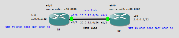
Routers are running OSPF on link connected to e1/1 and isis on link connected to e0/0. Look at the picture below, it shows the two basic packets (HELLO PACKET) captured on both links.
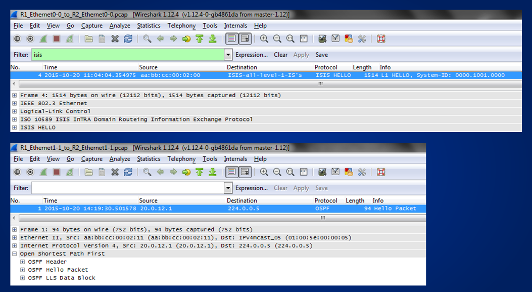
What is the big difference between the twos? To answer read the captures:
– we have an Ethernet frame
-> for OSPF the used frame is Ethernet II
-> for IS-IS the used frame is an IEEE 802.3 frame
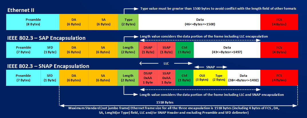
Look below to have an idea of the difference between three ethernet frame format:
then:
– what is inside the two captured ethernet frames?
-> in case of OSPF we have an IP Packet and inside the IP Packet we have an OSPF Hello Packet
-> in case of IS-IS we HAVE NOT an IP Packet, but instead the IS-IS Hello Packet is directly encapsulated into the ethernet frame.
One of the biggest thing to understand about IS-IS is that it is natively capable of distributing routing information for different Network Layer Protocols, routing for IP is only one of the application of IS-IS.
Now, as I’ve already said let’s start with simple things.
First thing I learned is that IS-IS is directly encapsulated in an 802.3 SAP frame then IS-IS messages are not IP packets.
I will remove the OSPF link from my basic topology to end with this new small network made of nine routers and two switches:
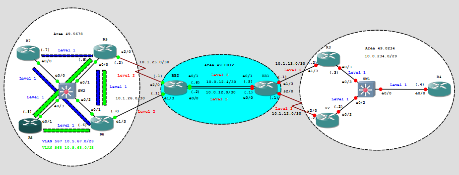
Let’s start to configure the network with all necessary things to have full IP reachability granted by IS-IS routing protocol, our target is to have IP communication between routers belonging to area 49.5678 in the left side of the network and routers belonging to area 49.0234 in the right side.
As a general rule, to speak IS-IS that is a link-state protocol, each router must be identified in the network as a node.
In a pure IP world, with routing application like OSPF running on top of IP protocol, routers are identified by a router-id (typically an IP address of some Loopback interface) and each interface that must partecipate in the routing protocol must have an ip address assigned to it.
IS-IS uses instead ONE OSI ADDRESS to identify a node in the network, the big difference with IP based routing protocol is that we will have ONE OSI ADDRESS per router and no other OSI addresses will be used on the interfaces connecting routers. You can read tons of books and documents about the general format of an OSI address, instead we can keep things simple and say that a speaking-isis router will be identified only by a NETWORK ENTITY TITLE (NET), the NET, just to know, it’s simply a subset of an OSI address:
NET [HEX dotted string] = <AREA-ID|SYSTEM-ID|NSEL>
AREA-ID variable size (1 <-> 13 bytes) – First byte is called AFI (Address Family Identifier) and tells how to interpret the remaining bytes of the AREA-ID. There are 4 well-known AFI, of this 4 AFI values, the only one we need to remember to route IP over IS-IS in our Autonomous System (AS) is AFI = 49. Why? Because AREA-ID have only local significance inside the AS, and AFI = 49 identifies PRIVATE AREAS inside an AS. The other 3 AFI values describe international standard and numbering plan, that are not interesting for my short discussion about routing IP over IS-IS, then all the routers of my test will have an AREA-ID starting with 49.XXXX….. where XXXX will identify some way the group of routers belonging to that area. Routers R2,R3,R4 belong to AREA 49.0234, routers BB1 and BB2 belong to AREA 49.0012 and routers R5,R6,R7,R8 belong to AREA 49.5678.
SYSTEM-ID variable size (1 <-> 8 bytes) – The SYSTEM-ID is the piece of the NET that makes the NET unique for each routers. It’s variable in length because to add flexibility making IS-IS capable of routing not only IP, but also many other network layer protocols, the ISO specification allows to have a variable size. All routers manufacturers agreed to instructs their codes to use SYSTEM-ID not longer than 6 bytes. There are many methods to grant uniqueness to the SYSTEM-ID, here I will use a method that consists to translate IP Loopbacks assigned to each routers in a 6 bytes string. For example router BB1 will have a Loopback0 IP address 99.0.0.1 and BB2 99.0.0.2, SYSTEM-IDs will be 0099.0000.0001 and 0099.0000.0002 router R2 will have a Loopback0 address 2.2.2.2 and a SYSTEM-ID 0002.0202.0002, router R3 3.3.3.3 will have a SYSTEM-ID 0003.0303.0003, the logic I found is to take the first octet of the IP address and find space for it in the first two bytes (using decimal digit as hex digit), take the two central octets of the IP address and find space for them in the central two bytes of the SYSTEM-ID, take the last octet of the IP address and find space for it in the last two bytes of the SYSTEM-ID. Here the uniqueness is granted by the IP address schema used for Loopbacks IP addresses (that must to be different unless you like to have serious problem in your network – exception to this exists (for example multicast rendezvous point redundancy)).
NSEL (NETWORK SELECTOR) – 1 byte – MUST BE = 00 for all IS-IS implementation – 00 means “THIS SYSTEM”
Where is the NET configured? In IOS under the isis router process, in Junos under the Loopback0 interface under the branch family ISO.
Now I have all the elements to configure NETs on all routers. IOS give me the possibility to give a name to the ISIS process, ISIS processes with different names can communicate. I will choose router isis BB on routers BB1 and BB2, router isis LEFT under area 49.5678 and router isis RIGHT under area 49.0234
So far, I did nothing more than giving each router an OSI-ID (no isis info is flowing on the links) before moving to enable the links for IS-IS, it’s time to discuss shortly some concepts you can see looking at the topology; we see AREAs and LEVELs (Level-1 links and Level-2 Links).
What is an area used for in IS-IS? Like for all other link-state protocols each router running IS-IS share a common database structure, this structure is calculated locally by each routers based on the info that other routers send to each other. The database describes each node and how each node is connected to other nodes that share the same database.
In few words an area is used in IS-IS, like in OSPF, to reduce the database size, the network is divided into smaller portions called areas. Each router belonging to the same area share the same database. In OSPF the database is divided by area and a Special Area (AREA 0) is the gluing factor between all areas, every other not-zero-areas must be connected to area 0 to let all info flowing from one area and reaching remote areas behind area 0.
In IS-IS the logical use of areas and database is different, here some concepts that summarize this difference:
1] ROUTERS (AND ALL THEIR INTERFACES) BELONG TO ONLY ONE AREA
2] THERE IS NO SPECIAL AREA
3] ROUTERS BUILD TOPOLOGICAL INFORMATION PER LEVEL (1 and/or 2) AND NOT PER AREA
4] LINKS CAN BE MARKED WITH THREE DIFFERENT FLAGS DESCRIBING THE LEVEL OF THE LINK (L1, L2 or L1-L2)
5] ALL ROUTERS CONNECTED BY LEVEL-1 LINK MUST BELONG TO THE SAME AREA
6] LEVEL-2 LINKS ARE THE GLUE BETWEEN THE AREAS (TWO ROUTERS IN DIFFERENT AREAS WILL BECOME ADJACENT ONLY IF THEY ARE CONNECTED BY LEVEL-2 LINKS)
7] BY DEFAULT, ROUTING INFO LEAKS FROM LEVEL-1 to LEVEL-2 DATABASE, NO LEAKING EXISTS FROM LEVEL-2 to LEVEL-1
8] LEVEL-2 LINKS MUST BE CONTIGOUS BETWEEN ROUTERS, CONTIGOUS LEVEL-2 LINKS FORM THE IS-IS BACKBONE
Putting all the seven concepts over my test network results in something like this: R5,R6,R7,R8 will share the same LEVEL-1 database, R5,R6,BB2,BB1,R2,R3 will share the same LEVEL-2 database, R2,R3,R4 will share the same LEVEL-1 database. This means that the left-group of routers will have a common view about how they are locally connected inside their same common area, the same happens for the right-group of routers, a similar thing happens to the middle group of routers connected by level-2 links, R5,R6,BB2,BB1,R2,R3 will have a common view about how they are connected by level-2 links across all three different areas, in this latter case topological information is disjointed from areas.
R5,R6,R2 and R3 play a role similar to OSPF’s ABRs, in other words traffic from routers in an area, must pass through Level-2 backbone links to reach routers in different areas.
In IS-IS protocol hierarchy is given by levels and not by areas like in OSPF.
Let’s activate links for IS-IS step by step and let’s see how adjacency are formed and how database is built.
To enable links for IS-IS the command to use is “ip router isis <NAME>”
BB1#sh run int e0/1 | b interface
interface Ethernet0/1
ip address 10.0.12.5 255.255.255.252
ip router isis BB ==> enable IS-IS process BB on the link
isis circuit-type level-2-only ==> Flags the link as level-2 only link
BB1#sh run int e0/0 | b interface
interface Ethernet0/0
ip address 10.0.12.1 255.255.255.252
ip router isis BB
isis circuit-type level-2-only
When links are enabled for IS-IS, first thing router does is sending the basic message – an HELLO message – to discover some other is-is speaking router.
Hello can be seen with a debug
BB1#debug isis adj-packets
IS-IS Adjacency related packets debugging is on for router process BB
BB1#
*May 26 08:16:19.291: ISIS-Adj: Sending L2 LAN IIH on Ethernet0/0, length 1497
*May 26 08:16:20.665: ISIS-Adj: Sending L2 LAN IIH on Ethernet0/1, length 1497
*May 26 08:16:27.474: ISIS-Adj: Sending L2 LAN IIH on Ethernet0/0, length 1497
*May 26 08:16:29.414: ISIS-Adj: Sending L2 LAN IIH on Ethernet0/1, length 1497
*May 26 08:16:35.628: ISIS-Adj: Sending L2 LAN IIH on Ethernet0/0, length 1497
*May 26 08:16:38.556: ISIS-Adj: Sending L2 LAN IIH on Ethernet0/1, length 1497
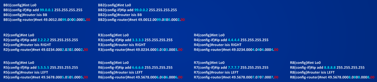
or can be captured by using wireshark, below you can see the captured hello packet on the interface e0/1 of BB2 receiving the Hello packets sent by BB1:
In the above picture you can see the real packet captured by wireshark and the corresponding format of the Hello Packet. First of all, some math about the size of the IS-IS PDU. The captured ethernet frame is 1514 bytes (1518 bytes of a standard 802.3 SAP Ethernet – 4 bytes of FCS (Wireshark doesn’t show the FCS)), in these 1514 bytes we have:
Destination MAC address = 01:80:c2:00:00:15 (ISIS-all-level-2-Intermediate Systems) (6 bytes)
Source MAC address = MAC of the port sending the Hello (6 bytes)
length = 1500 (2 bytes) ==> counts 3 bytes of LLC encapsulation + 1497 bytes of IS-IS PDU
1497 BYTES IS THE MAXIMUM length of an OSI IS-IS PDU that can fit into an 802.3 sap ethernet frame. Each IS-IS message has a COMMON HEADER OF 8 bytes, the remaining 1489 bytes leave space (in this case of Hello Packet) for an HELLO HEADER of 19 bytes and then for 1470 bytes of HELLO DATA info. It’s interesting to see (look also at the above debug messages) that the HELLO PACKET is padded up to the maximum size possible, the padding is realized using special Type (1 byte) length (1 byte) Value Structures – TLV#8 with 255 bytes of padding data for a total of 257 bytes each (but the last is 163 bytes of data (for a total of 165 bytes) to fit the frame up to 1470 bytes).
This padding is used by IS-IS to check the MTU of the link, it’s worth to remember that since IS-IS packets are not IP packets, IS-IS cannot use the service of the IP protocol in term of fragmentation.
NOTE: TLV structures are the fundamental piece of informations encoded in each IS-IS message exchanged between IS-IS speaking routers. Each TLV has a specific meaning, different type of IS-IS messages use different type of TLVs, the same type of TLV can be used in different IS-IS messages.
The most relevant information sent in the HELLO Message are:
1) PDU Type – in this case we have PDU TYPE of 16 meaning L2 LAN HELLO (other possible values are 15 L1 LAN HELLO, 17 P2P (Point-to-Point) HELLO)
2) Circuit Type 0x01=Level-1-only 0x02=Level-2-only 0x03=Level-1-2
3) Source-ID is the System-ID of the device sending the hello, in this case is 0099.0000.0001
4) Holding Time (2 bytes) = 30 seconds – IS-IS doesn’t send hello interval info in its Hello packets, each IS-IS routers sends only HOLD TIME information, this timer is used by the receiving router to declare the neighboring systems dead if no hello packet is received within the Hold Timer interval. Each received Hello Packet resets the Hold Time. Important thing to remember is that each router sets the Hold Timer independently from other routers and two neighboring routers can have different hold timer values, this doesn’t prevent routers to become neighbors. Each Implementation of IS-IS then use a factor called Multiplier (its value its typically 3), dividing Hold Time/Multiplier results in the used Hello Interval, IOS uses 30s/3=10 sec. JunOs uses 27s/3 = 9 sec. Multiplier can be set using subinterface command both in IOS and in JunOs.
BB1(config)#int e0/0
BB1(config-if)#isis hello-interval ?
<1-65535> Hello interval value
minimal Holdtime 1 second, interval depends on multiplier ==> set HoldTime to 1 second, using a multiplier factor (default = 3) lets me have a subsecond Hello-Interval.
BB1(config-if)#isis hello-multiplier ?
<3-1000> Hello multiplier value
BB1(config-if)#isis hello-multiplier 5 ?
level-1 Specify hello multiplier for level-1 IIHs
level-2 Specify hello multiplier for level-2 IIHs
NOTE: If you look at the above debug messages, it can be seen that HELLOs are not sent EXACTLY at 10 seconds interval, but the time between an hello and the next one is always less than 10 seconds, this is not an error, but a protection mechanism implemented both in IOS and JunOS to prevent an Hello Synchronization Problem, in few words, if you have many routers on the same LAN, or a Central HUB router keeping many neighborship, routers on LAN or this central router could be overwhelmed by many concurrent Hello Packets, if router has not enough buffer space it could not be able to process all the hello packets and drop some of them. The solution is simply implementing a Jitter on the Hello Interval and make this jitter randomic. IOS and JunOs both apply a random jitter, decreasing the hello interval by a quantity of time between 5% and 25% at random, before scheduling the sending of the next-hello. For example if next hello on a link should be sent a time T1, hello packet is instead sent at T1-R1 where R1 is the random jitter. In this way it’s very difficult to have some hellos hitting at the same time the CPU of a router. The same logic apply in IS-IS to all elements that are subjects to periodic resending (for example CSNP packets).
5) Designated System-ID ==> This is the Pseudo-Node-ID (in this case 0099.0000.0001.01) on the LAN.
All this information sent in Hello Message is used by IS-IS routers to discover neighbors. Before moving on about how this is accomplished on LAN circuit, it’s time to explain what a Designated IS is on the LAN. So far I configured IS-IS support only on the two ehternet links of BB1:
BB1#sh run int e0/0 | b interface
interface Ethernet0/0
ip address 10.0.12.1 255.255.255.252
ip router isis BB
isis circuit-type level-2-only
end
BB1#sh run int e0/1 | b interface
interface Ethernet0/1
ip address 10.0.12.5 255.255.255.252
ip router isis BB
isis circuit-type level-2-only
end
From an IP protocol point of view these are point-to-point /30 links, but they are still ethernet broadcast link, so even on this type of circuit (by default) a Designated IS will be elected (this is similar to what happens in OSPF, by default you will have a Designated Router on broadcast link). The concept of a pseudo-node is a way to let the protocol scaling in too populated LANs. This problem is a well known one in scenario where some nodes (in this case routers) must establish a relationship between each other, if you have N routers on a LAN segments and each router must establish a neighborship with all other routers, the number of relations between all the routers will be N*(N-1)/2, something that increase with a N*N factor. For example if you have 10 routers on a LAN you will have 45 neighborships and on all this neighborship routers will send Hello Packets and other Routing Control Packets, wasting some way the bandwidth of the LAN. Having a PSEUDO-NODE helps in reducing this overhead. Now here I was considering only two routers then I will have no benefit but, as already said, by default routers don’t know if on a broadcast link (like ethernet) they will see only one other router or many other routers, then a pseudo-node will be elected.
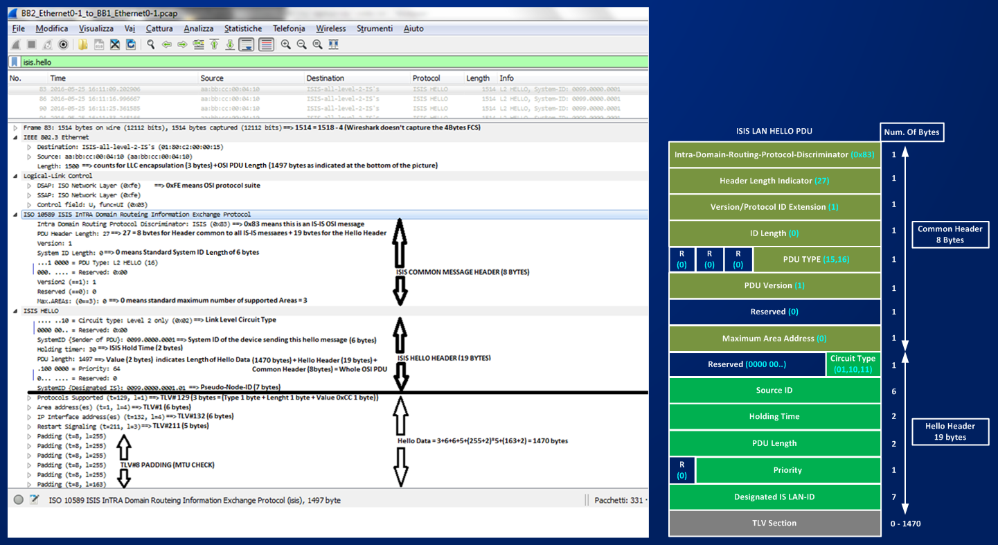
What is a PSEUDO-NODE? It’s a way to represent the LAN and how routers are connected on the LAN, if I consider BB1 and BB2 and their connecting links e0/0 and e0/1:
Like shown in the picture, LANs are abstractions that are represented in the isis database like if it were node to which BB1 and BB2 are connected. These abstractions helps in reducing the number of neighborship, instead of having N*N problem now we have only a linear problem growing with the number N of nodes. But an abstraction does not generate hellos, so one of the router on the LAN must behave as if it was the LAN itself. This router is the PSEUDO-NODE. Let’s look back at the captured Hello packet sent by BB1, you can see that when BB1 sends out the HELLO it writes 0099.0000.0001.01 in the Designated-IS field of the Hello Header, it believes at the beginning to be the DIS.
Look now at how element are described in the isis database, so far we have not too much reading in the database of BB1, because we have no neighbor and only two links enabled for IS-IS:
BB1#show isis database
Tag BB:
IS-IS Level-1 Link State Database:
LSPID LSP Seq Num LSP Checksum LSP Holdtime ATT/P/OL
BB1.00-00 * 0x00000018 0xD081 796 0/0/0
IS-IS Level-2 Link State Database:
LSPID LSP Seq Num LSP Checksum LSP Holdtime ATT/P/OL
BB1.00-00 * 0x00000018 0x8054 704 0/0/0
BB1#show isis hostname
Level System ID Dynamic Hostname (BB)
* 0099.0000.0001 BB1
First thing I can note is that even though I have no Level-1 enabled link on BB1, after enabling IS-IS for level-2 only on BB1, BB1 creates anyway the basic element that describes itself both in L1 and L2 database. The difference is that the element describing BB1 in the L1 database will not have any other info.
BB1#show isis database detail
Tag BB:
IS-IS Level-1 Link State Database:
LSPID LSP Seq Num LSP Checksum LSP Holdtime ATT/P/OL
BB1.00-00 * 0x00000019 0xCE82 849 0/0/0
Area Address: 49.0012
NLPID: 0xCC
Hostname: BB1
IS-IS Level-2 Link State Database:
LSPID LSP Seq Num LSP Checksum LSP Holdtime ATT/P/OL
BB1.00-00 * 0x00000019 0x7E55 884 0/0/0
Area Address: 49.0012
NLPID: 0xCC
Hostname: BB1
IP Address: 10.0.12.5
Metric: 10 IP 10.0.12.0 255.255.255.252
Metric: 10 IP 10.0.12.4 255.255.255.252
The basic element in the IS-IS database is called Link State Protocol Data Unit (LSP in short), each LSP is inserted in the database with an identifier, this identifier is the LSPID, in this case I see an LSPID = BB1.00-00, the general structure of LSP-ID is this one:
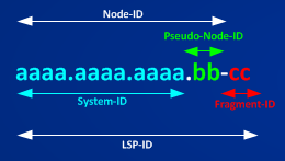
LSP-ID is formed by System-ID (6 bytes), the Pseudo-Node-ID (1 byte) that represent the Designated-IS and the Fragment-ID (1 byte) something that IS-IS uses to manage fragmentation of its messages (if the value is 00, LSP is not fragmented).
Why do we read BB1.00-00 instead? Because IS-IS implements an extension that helps us in having a more readable database mapping the System-ID to the hostname of the router. This extension uses a special TLV#137 structure (Type 137, length (1 byte), Value (1..255 bytes)) that carries the hostname of the router as its value.
The Pseudo-Node-ID is used in this way: if its value is 0x00 then the LSP-ID represents a REAL ROUTER in the Network, if its value is not 0x00 it represents the Virtual Router representing the LAN to which real routers are connected. In the database I see only the LSP-ID BB1.00-00 (that can be translated in 0099.0000.0001.00-00) meaning that the LSPID represent the real BB1 router. After adjacency with neighbor routers will be established we must expect an LSP-ID representing the LANs between BB1 and BB2.
Let’s complete the reading of the element in the database of BB1, before making adjacency with BB2 to establish. The general structure of an LSP is:
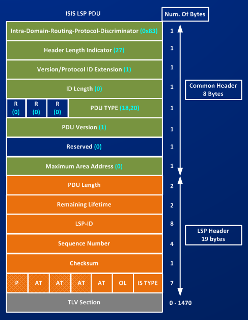
The structure shown in the picture is formed by an IS-IS speaking router when it must send this LSP to other neighbor, we have an header of 8 byte common to all IS-IS messages, and an LSP-Header of 19 bytes that describes specifically the Link State PDU, some of these element are used to build the entry in the database:
1) LSP-ID is the pointer to the entry in the database
2) LSP Seq Num – Sequence-Number is used to verify if an LSP is newer or older
3) Checksum verify the integrity of the PDU
4) LSP Hold Time is the Remaining Life Time of the LSP (default is 1200 sec. (20 min.))
5) ATT/P/OL are respectively the ATTach (DEFAULT) bit, the Partition Bit, and the OverLoad Bit
You can see in the last byte of the LSP-Header (the Attribute Block) that there are 4 Attach Bits, this is an historical inheritance of the ISO specification where IS-IS was made to support Multitopology databases, in other words the specification made IS-IS capable of calculating 4 different databases based on different network information that were:
a) lowest bit error rate on a link
b) monetary cost of a link
c) lowest delay on a link
d) use this last one if you are not sure about what of the first three to use (default metric)
Fortunately for our mental sanity this sort of Multidimensional Database has never been implemented and all IS-IS implementations use only one database based on the DEFAULT information, the cost (metric) of a link. Then the ATT bit you read in some shows/debug of routers is the ATT bit corresponding to the 4th bit (starting from right) after the OL bit.
What is the meaning of the ATTach bit? This bit is set only by L1L2 routers in their L1 LSP, this information allows routers in an area to know that a node in the area is connected to other areas by level-2 link.
The Partition bit can be easily ignored because no existing implementation use it at lest for IP protocol, this bit should indicate if a router has the capability to repair a broken L1 area using L2 area – we can safely ignoring this bit.
The Overload Bit is a tool used at the beginning to protect the network from not-too-much memory capable routers, low-memory routers may have only partial database information, in that case all the Link State game based on the distributed database between nodes could be corrupted. Setting the OL bit takes a node out of the network topology and this node cannot be used as a TRANSIT node, the node instead can still be used to reach subnets directly attached to the node itself. Today routers should not have low-memory problems, the OL bit is still used to protect the network from transient issues (router reloads, software defects…, IGP vs. BGP synchronization), OL bit can be permanently marked or marked and then removed after some time or marked and removed after all BGP sessions on a router are up.
router isis BB
set-overload-bit
router isis BB
set-overload-bit on-startup [time-interval (sec.)]
router isis BB
set-overload-bit on-startup wait-for-bgp
NOTE: this is the same concept of max-metric router-lsa on-startup for OSPF
Let’s move down in the show isis database of BB1, after inserting information that will be used to build the LSP-header, BB1 insert additional info to describe itself in the database, first thing it writes is the area address to which it belongs (49.0012) this is the base element of TLV#1 (Area Address), then we see NLPID = 0xCC (meaning supported protocol is IPv4), this is the base element for TLV#129 (Supported Protocol), next comes Hostname: BB1 and I’ve already said this is the base element of TLV#137 that is used by IS-IS to implement the hostname-to-system-id mapping, next comes a first IP information read as IP Address: 10.0.12.5, what is this IP info? This IP address is the base element for TLV#134 (Traffic Engineering Router-ID), this IP play the same role as an IP-router-ID, this address is defined as the highest IP address configured on a interface enabled for IS-IS, if an IS-IS enabled loopback address is present, the highest Loopback’s address will be used, otherwise the highest IP address of an IS-IS enabled interface will be used. To see how this IP address changes in the database let’s follow this test:
I shut down interface e0/1 removing it from IS-IS topology:
BB1#show isis database level-2 detail
Tag BB:
IS-IS Level-2 Link State Database:
LSPID LSP Seq Num LSP Checksum LSP Holdtime ATT/P/OL
BB1.00-00 * 0x00000001 0xAE3D 1051 0/0/0
Area Address: 49.0012
NLPID: 0xCC
Hostname: BB1
IP Address: 10.0.12.5
Metric: 10 IP 10.0.12.0 255.255.255.252
Metric: 10 IP 10.0.12.4 255.255.255.252
BB1#sh run int e0/1 | b interface
interface Ethernet0/1
ip address 10.0.12.5 255.255.255.252
ip router isis BB
isis circuit-type level-2-only
BB1(config)#int e0/1
BB1(config-if)#shut
*Jun 2 11:07:30.992: %LINK-5-CHANGED: Interface Ethernet0/1, changed state to administratively down
*Jun 2 11:07:31.999: %LINEPROTO-5-UPDOWN: Line protocol on Interface Ethernet0/1, changed state to down
BB1#show isis database level-2 detail
Tag BB:
IS-IS Level-2 Link State Database:
LSPID LSP Seq Num LSP Checksum LSP Holdtime ATT/P/OL
BB1.00-00 * 0x00000002 0xD1CB 1175 0/0/0
Area Address: 49.0012
NLPID: 0xCC
Hostname: BB1
IP Address: 10.0.12.1 ==> Look how this is changed to the only one available IP address enabled on a IS-IS link (the e0/0 IP address)
Metric: 10 IP 10.0.12.0 255.255.255.252
If now I enabled IS-IS on the Loopback, this address will be changed to the Loopback0’s IP Address:
BB1#sh run int Lo0 | b interface
interface Loopback0
ip address 99.0.0.1 255.255.255.255
BB1(config)#int Lo0
BB1(config-if)#isis circuit-type level-2-only
BB1(config-if)#ip router isis BB
BB1#show isis database level-2 detail
Tag BB:
IS-IS Level-2 Link State Database:
LSPID LSP Seq Num LSP Checksum LSP Holdtime ATT/P/OL
BB1.00-00 * 0x00000003 0xB59D 1178 0/0/0
Area Address: 49.0012
NLPID: 0xCC
Hostname: BB1
IP Address: 99.0.0.1 ==> Lo0 is the new IP-Router-ID.
Metric: 10 IP 10.0.12.0 255.255.255.252
Metric: 10 IP 99.0.0.1 255.255.255.255
Above tests help me to understand the remaining IP information elements that are inserted by IOS in the IS-IS database of BB1, in short, IOS writes all subnets directly connected to BB1 and that are enabled for IS-IS protocol. This is the base information element that build TLV#128 (Internal IP Reachability).
After describing how a node is encoded in IS-IS database I can complete the elements reported in the HELLO PDU, I described down to the Designated-IS, after that starts the Hello Data portion of the PDU, then there is a list of TLVs, I have already described some of them, specifically TLV#129 (Supported Protocol) and TLV#1 (Area Address), to complete the reading only one TLV remains to explain in the HELLO PDU, this TLV is TLV#132 (IPv4 Interface Address), this TLV is used in the Hello PDU to tell router at the other side of the link which is (are) the IP address configured on the interface of the router sending this HELLO PDU, I can see that in this HELLO PDU this TLV brings IP address 10.0.12.5 that is e0/1’s IP address. When other router on this link will receive this Hello it will check this TLV against the list of IP addresses configured on its receiving interface, and if it doesn’t find a common IP subnet, adjacency will not form. This TLV is used then like a sort of common subnet checking.
It’s time to recap what I’ve learned and done so far. I considered routers BB1 and BB2 connected by a couple of ehternet link configured with /30 IP subnets, I activated IS-IS protocol on both links and on the Loopback0 interfaces of BB1, I realized that when enabling the protocol BB1 starts discovering neighbors sending Hello Packet with a specific format based on IS-IS circuit-type, I learned that Hello Packets are a specific type of IS-IS messages and that IS-IS messages have a common header (of 8 bytes) and specific TLV sections. Furthermore, as soon as IS-IS is enabled on a link of a router, IOS builds entries in L1 and L2 database describing the router itself in this databases, information inserted in the database are then used later by IOS to build the needed TLVs that must be inserted in the specific IS-IS messages. Also, broadcast LAN circuits that are enabled for IS-IS are described by PSEUDO-NODE elements in the IS-IS database, this pseudo-node acts like a virtual router where real routers are connected to.
Based on what I’ve learned so far, next move is to enable IS-IS on BB2 too and see how sending and receipt of Hello Packets builds adjacency between routers. I will capture packets on both routers. To reduce the messages and for better readability I will start activating only one link (e0/0) and the Loopback interfaces.
BB1#sh run int Lo0 | b interface
interface Loopback0
ip address 99.0.0.1 255.255.255.255
ip router isis BB
isis circuit-type level-2-only
BB1#show run int e0/0 | b interface
interface Ethernet0/0
ip address 10.0.12.1 255.255.255.252
ip router isis BB
isis circuit-type level-2-only
BB1#sh run int e0/1 | b interface
interface Ethernet0/1
ip address 10.0.12.5 255.255.255.252
ip router isis BB
shutdown
isis circuit-type level-2-only
BB1#sh run | s r i
router isis BB
net 49.0012.0099.0000.0001.00
BB1#sh int e0/0 | i Hard
Hardware is AmdP2, address is aabb.cc00.0400 (bia aabb.cc00.0400)
BB1#debug isis adj-packets
BB2#sh run int Lo0 | b interface
interface Loopback0
ip address 99.0.0.2 255.255.255.255
ip router isis BB
isis circuit-type level-2-only
BB2#sh run int e0/0 | b interface
interface Ethernet0/0
ip address 10.0.12.2 255.255.255.252
ip router isis BB
shutdown
isis circuit-type level-2-only
BB2#sh run int e0/1 | b interface
interface Ethernet0/1
ip address 10.0.12.6 255.255.255.252
ip router isis BB
shutdown
isis circuit-type level-2-only
BB2#sh int e0/0 | i Hard
Hardware is AmdP2, address is aabb.cc00.0600 (bia aabb.cc00.0600)
BB2#debug isis adj-packets
After enabling IS-IS on a link and starting to send Hellos, IS-IS must verify bidirectional capabilities of the link, this check is accomplished using a 3-way handshake mechanism based on the exchange of hello packets. Looking at the debugs and captured packets on the wire we can see this exchange:
BB1(config)#int e0/0
BB1(config-if)#no shut
*Jun 2 13:45:56.815: %LINK-3-UPDOWN: Interface Ethernet0/0, changed state to up
*Jun 2 13:45:57.820: %LINEPROTO-5-UPDOWN: Line protocol on Interface Ethernet0/0, changed state to up
Activating e0/0 interface on BB1 makes BB1 starts to send Hello on the link.
*Jun 2 13:45:57.820: %LINEPROTO-5-UPDOWN: Line protocol on Interface Ethernet0/0, changed state to up
*Jun 2 13:45:57.820: ISIS-Adj: Et0/0: Current SYNC state: Normal(1). Event: No SYNC required(1)
*Jun 2 13:45:57.820: ISIS-Adj: Et0/0: New SYNC state: Normal(1)
*Jun 2 13:45:57.820: ISIS-Adj: Et0/0: Current SYNC state: Normal(1). Event: No SYNC required(1)
*Jun 2 13:45:57.820: ISIS-Adj: Et0/0: New SYNC state: Normal(1)
*Jun 2 13:45:57.830: ISIS-Adj: Sending L2 LAN IIH on Ethernet0/0, length 1497
*Jun 2 13:46:07.674: ISIS-Adj: Sending L2 LAN IIH on Ethernet0/0, length 1497
*Jun 2 13:46:15.686: ISIS-Adj: Sending L2 LAN IIH on Ethernet0/0, length 1497
*Jun 2 13:46:24.617: ISIS-Adj: Sending L2 LAN IIH on Ethernet0/0, length 1497
*Jun 2 13:46:26.761: ISIS-Adj: Rec L2 IIH from aabb.cc00.0600 (Ethernet0/0), cir type L2, cir id 0099.0000.0002.02, length 1497, ht(30)
*Jun 2 13:46:26.761: ISIS-Adj: New adjacency, level 2 for aabb.cc00.0600
*Jun 2 13:46:26.770: ISIS-Adj: Sending L2 LAN IIH on Ethernet0/0, length 1497
*Jun 2 13:46:27.768: ISIS-Adj: Rec L2 IIH from aabb.cc00.0600 (Ethernet0/0), cir type L2, cir id 0099.0000.0002.02, length 1497, ht(30)
*Jun 2 13:46:27.768: ISIS-Adj: he_knows_us 1, old state 1, new state 0, level 2
*Jun 2 13:46:27.768: ISIS-Adj: L2 adj count 1
*Jun 2 13:46:27.768: ISIS-Adj: L2 adjacency state goes to Up
*Jun 2 13:46:27.768: ISIS-Adj: Run level-2 DR election for Ethernet0/0
*Jun 2 13:46:27.768: ISIS-Adj: New level-2 DR 0099.0000.0002 on Ethernet0/0
*Jun 2 13:46:27.772: ISIS-Adj: Sending L2 LAN IIH on Ethernet0/0, length 1497
*Jun 2 13:46:28.768: ISIS-Adj: Rec L2 IIH from aabb.cc00.0600 (Ethernet0/0), cir type L2, cir id 0099.0000.0002.02, length 1497, ht(10)
Activating e0/0 interface on BB2 makes BB2 starting to send hellos on the link as well.
BB2(config)#int e0/0
BB2(config-if)#no shut
*Jun 2 13:46:25.755: %LINK-3-UPDOWN: Interface Ethernet0/0, changed state to up
*Jun 2 13:46:26.760: %LINEPROTO-5-UPDOWN: Line protocol on Interface Ethernet0/0, changed state to up
*Jun 2 13:46:26.760: ISIS-Adj: Et0/0: Current SYNC state: Normal(1). Event: No SYNC required(1)
*Jun 2 13:46:26.760: ISIS-Adj: Et0/0: New SYNC state: Normal(1)
*Jun 2 13:46:26.760: ISIS-Adj: Et0/0: Current SYNC state: Normal(1). Event: No SYNC required(1)
*Jun 2 13:46:26.760: ISIS-Adj: Et0/0: New SYNC state: Normal(1)
*Jun 2 13:46:26.761: ISIS-Adj: Sending L2 LAN IIH on Ethernet0/0, length 1497
*Jun 2 13:46:26.770: ISIS-Adj: Rec L2 IIH from aabb.cc00.0400 (Ethernet0/0), cir type L2, cir id 0099.0000.0001.01, length 1497, ht(30)
*Jun 2 13:46:26.770: ISIS-Adj: New adjacency, level 2 for aabb.cc00.0400
*Jun 2 13:46:27.768: ISIS-Adj: Sending L2 LAN IIH on Ethernet0/0, length 1497
*Jun 2 13:46:27.773: ISIS-Adj: Rec L2 IIH from aabb.cc00.0400 (Ethernet0/0), cir type L2, cir id 0099.0000.0002.02, length 1497, ht(30)
*Jun 2 13:46:27.773: ISIS-Adj: he_knows_us 1, old state 1, new state 0, level 2
*Jun 2 13:46:27.773: ISIS-Adj: L2 adj count 1
*Jun 2 13:46:27.773: ISIS-Adj: L2 adjacency state goes to Up
*Jun 2 13:46:27.773: ISIS-Adj: Run level-2 DR election for Ethernet0/0
*Jun 2 13:46:27.773: ISIS-Adj: New level-2 DR 0099.0000.0002 on Ethernet0/0
*Jun 2 13:46:28.769: ISIS-Adj: Sending L2 LAN IIH on Ethernet0/0, length 1497
The following picture shows the list of exchanged and captured PDUs, and the meaningful HELLOs are expanded to see the different information added to HELLO PDUs when routers start to see each others.
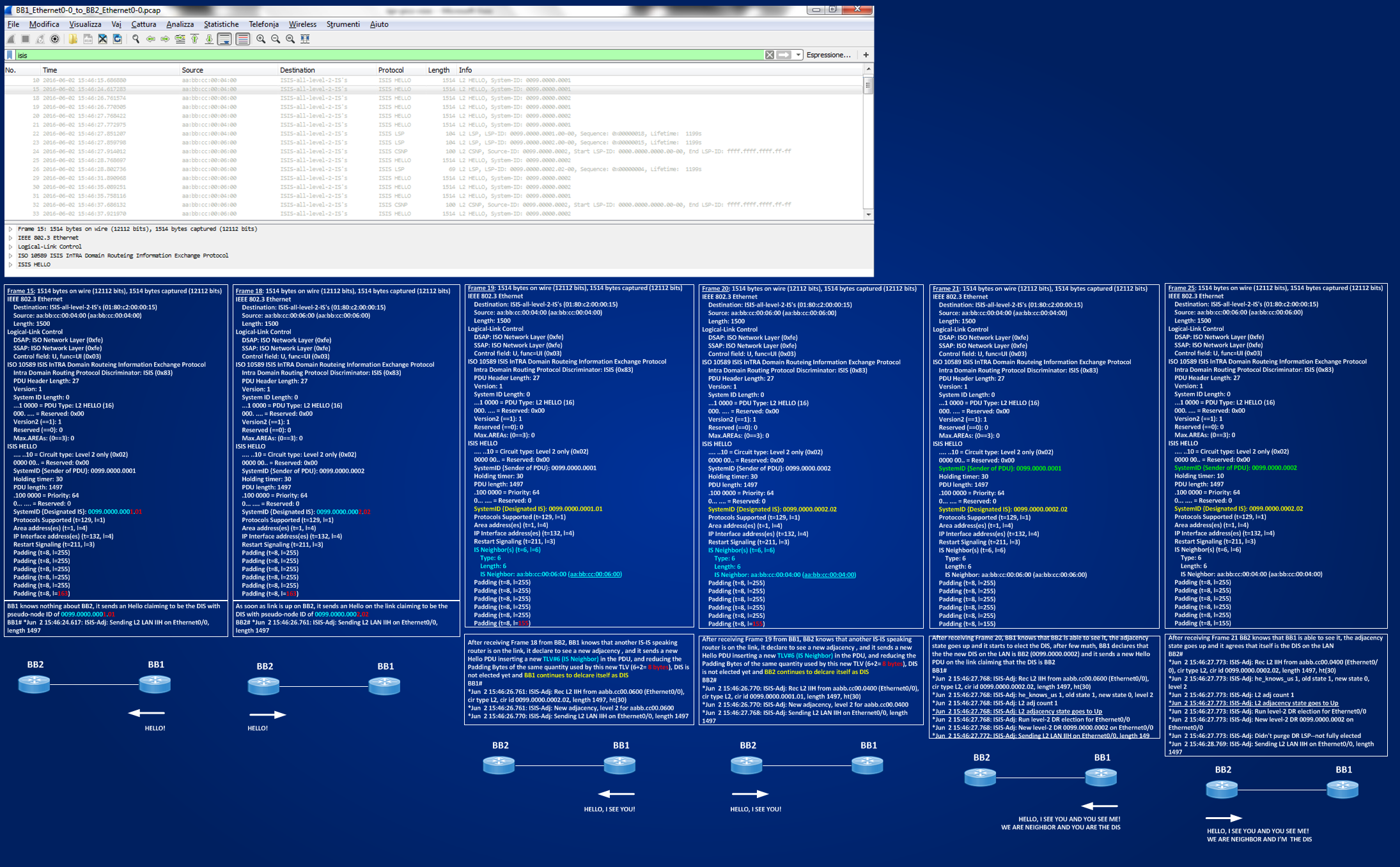
Looking at the picture it should be clear how after discovering each other on the link, routers start a DIS election – a matter of priority values in the interval 0-127 (higher ones win) and SNPA values (higher MAC values win the contest if priority tie), each routers calculates locally the DIS based on message exchanged by Hello PDUs – once the adjacency is up routers starts to exchange LSP to synchronize their database. This 3-way handshaking mechanism is based on the insertion in the Hello PDU of a specific TLV#6 (IS Neighbor) that describes the MAC addresses (Subnetwork Point of attachment in OSI terms) that can be seen on the LAN circuit by the router that is sending the Hello.
Now I enable also the second link between BB1 and BB2 and then I will look to the calculated database.
BB2(config)#int e0/1
BB2(config-if)#no shut
*Jun 3 09:59:26.741: %LINK-3-UPDOWN: Interface Ethernet0/1, changed state to up
*Jun 3 09:59:27.744: %LINEPROTO-5-UPDOWN: Line protocol on Interface Ethernet0/1, changed state to up
BB1(config)#int e0/1
BB1(config-if)#no shut
BB2(config-if)#
*Jun 3 09:59:30.741: %LINK-3-UPDOWN: Interface Ethernet0/1, changed state to up
*Jun 3 09:59:31.744: %LINEPROTO-5-UPDOWN: Line protocol on Interface Ethernet0/1, changed state to up
BB1#show isis database
Tag BB:
IS-IS Level-1 Link State Database:
LSPID LSP Seq Num LSP Checksum LSP Holdtime ATT/P/OL
BB1.00-00 * 0x0000000E 0xE477 941 0/0/0
IS-IS Level-2 Link State Database:
LSPID LSP Seq Num LSP Checksum LSP Holdtime ATT/P/OL
BB1.00-00 * 0x00000011 0x43EB 1189 0/0/0
BB2.00-00 0x00000012 0x71B8 1033 0/0/0
BB2.01-00 0x0000000D 0x5CA4 421 0/0/0
BB2.02-00 0x0000000E 0x53AB 959 0/0/0
BB2#sh isis database
Tag BB:
IS-IS Level-1 Link State Database:
LSPID LSP Seq Num LSP Checksum LSP Holdtime ATT/P/OL
BB2.00-00 * 0x0000000E 0xEB6E 837 0/0/0
IS-IS Level-2 Link State Database:
LSPID LSP Seq Num LSP Checksum LSP Holdtime ATT/P/OL
BB1.00-00 0x00000011 0x43EB 1163 0/0/0
BB2.00-00 * 0x00000012 0x71B8 1011 0/0/0
BB2.01-00 * 0x0000000E 0x5AA5 1186 0/0/0
BB2.02-00 * 0x0000000E 0x53AB 936 0/0/0
It’s easy to see how the level-2 databases are identical, this means that databases are synchronized and that BB1 and BB2 have the same topology view of the network they are connected to. Interesting to see that there are 4 LSP-ID in the database, the first two BB1.00-00 and BB2.00-00 represent real nodes, the last two BB2.01-00 and BB2.02-00 represent the two pseudo-nodes of the two broadcast LAN segment interconnecting BB1 and BB2. Let’s look at the detail of the databases.
BB1#show isis database detail
Tag BB:
IS-IS Level-1 Link State Database:
LSPID LSP Seq Num LSP Checksum LSP Holdtime ATT/P/OL
BB1.00-00 * 0x0000000E 0xE477 799 0/0/0
Area Address: 49.0012
NLPID: 0xCC
Hostname: BB1
IS-IS Level-2 Link State Database:
LSPID LSP Seq Num LSP Checksum LSP Holdtime ATT/P/OL
BB1.00-00 * 0x00000011 0x43EB 1048 0/0/0
Area Address: 49.0012
NLPID: 0xCC
Hostname: BB1
IP Address: 99.0.0.1
Metric: 10 IP 99.0.0.1 255.255.255.255
Metric: 10 IP 10.0.12.0 255.255.255.252
Metric: 10 IP 10.0.12.4 255.255.255.252
Metric: 10 IS BB2.01
Metric: 10 IS BB2.02
BB2.00-00 0x00000012 0x71B8 892 0/0/0
Area Address: 49.0012
NLPID: 0xCC
Hostname: BB2
IP Address: 99.0.0.2
Metric: 10 IP 99.0.0.2 255.255.255.255
Metric: 10 IP 10.0.12.0 255.255.255.252
Metric: 10 IP 10.0.12.4 255.255.255.252
Metric: 10 IS BB2.02
Metric: 10 IS BB2.01
BB2.01-00 0x0000000E 0x5AA5 1067 0/0/0
Metric: 0 IS BB2.00
Metric: 0 IS BB1.00
BB2.02-00 0x0000000E 0x53AB 817 0/0/0
Metric: 0 IS BB2.00
Metric: 0 IS BB1.00
BB2#show isis database detail
Tag BB:
IS-IS Level-1 Link State Database:
LSPID LSP Seq Num LSP Checksum LSP Holdtime ATT/P/OL
BB2.00-00 * 0x0000000E 0xEB6E 743 0/0/0
Area Address: 49.0012
NLPID: 0xCC
Hostname: BB2
IS-IS Level-2 Link State Database:
LSPID LSP Seq Num LSP Checksum LSP Holdtime ATT/P/OL
BB1.00-00 0x00000011 0x43EB 1068 0/0/0
Area Address: 49.0012
NLPID: 0xCC
Hostname: BB1
IP Address: 99.0.0.1
Metric: 10 IP 99.0.0.1 255.255.255.255
Metric: 10 IP 10.0.12.0 255.255.255.252
Metric: 10 IP 10.0.12.4 255.255.255.252
Metric: 10 IS BB2.01
Metric: 10 IS BB2.02
BB2.00-00 * 0x00000012 0x71B8 917 0/0/0
Area Address: 49.0012
NLPID: 0xCC
Hostname: BB2
IP Address: 99.0.0.2
Metric: 10 IP 99.0.0.2 255.255.255.255
Metric: 10 IP 10.0.12.0 255.255.255.252
Metric: 10 IP 10.0.12.4 255.255.255.252
Metric: 10 IS BB2.02
Metric: 10 IS BB2.01
BB2.01-00 * 0x0000000E 0x5AA5 1091 0/0/0
Metric: 0 IS BB2.00
Metric: 0 IS BB1.00
BB2.02-00 * 0x0000000E 0x53AB 842 0/0/0
Metric: 0 IS BB2.00
Metric: 0 IS BB1.00
Looking at the details I can see that each real node is described by the same TLVs we had before establishing adjacency that, for example for BB1, are:
TLV#1 Area Address
Area Address: 49.0012
TLV#129 Supported Protocol
NLPID: 0xCC
Dynamic Hostname TLV#137
Hostname: BB1
TLV#134 IP Router-ID
IP Address: 99.0.0.1
TLV#128 IPv4 Internal Reachability
Metric: 10 IP 99.0.0.1 255.255.255.255
Metric: 10 IP 10.0.12.0 255.255.255.252
Metric: 10 IP 10.0.12.4 255.255.255.252
After adjacencies are up, to both real node descriptions is added a new TLV#2 IS Reachability that describes the neighbors to which the described node is connected. This TLV#2 has a very simple structure and list only the metric to reach the listed neighbor and the NODE-ID (System-ID+Pseudo-Node-ID) of the neighbor:
TLV#2 IS Reachability
Metric: 10 IS BB2.02
Metric: 10 IS BB2.01
Other interesting things are: PSEUDO-NODES are completely described only by TLV#2 and they have no IP info in the database, real nodes go to pseudo-nodes with a metric of 10, pseudo-nodes go to real nodes with ZERO metric, then IS-IS database describes nodes like shown in the following picture:
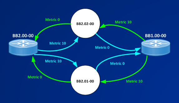
Pseudo-Nodes inherit their System-ID from the DIS elected on LAN segment (in this case is router BB2).
Now, when we have to do with point-to-point ethernet links with only two routers connected, this pseudo-node representation is not too much useful, instead it seems only a burden to complicate things. Can we suppress the pseudo-node generation in the database for point-to-point ethernet circuit? Answer is, yes, we can, but to understand how, we must review how things go for IS-IS on the other second supported link type, that is POINT-TO-POINT LINK (P2P). On P2P links TLV#6 cannot be used because we have no MAC addresses, IS-IS then uses another extension to implement 3-way handshaking, this other extension is TLV#240 Adjacency State. In its first elementary form the TLV is simply a 1 byte field describing the current status of an adjacency: (0x2 Down – 0x1 Initializing – 0x0 Up). I’m going to enable IS-IS on the serial link between BB1 and R2 and capture some packets.
BB1#sh run int se2/0 | b interface
interface Serial2/0
ip address 10.1.12.1 255.255.255.252
ip router isis BB
shutdown
encapsulation ppp
serial restart-delay 0
isis circuit-type level-2-only
R2#show run int se2/0 | b interface
interface Serial2/0
ip address 10.1.12.2 255.255.255.252
ip router isis RIGHT
shutdown
encapsulation ppp
serial restart-delay 0
isis circuit-type level-2-only
BB1(config)#int se2/0
BB1(config-if)#no shut
*Jun 4 11:53:55.542: %LINK-3-UPDOWN: Interface Serial2/0, changed state to up
*Jun 4 11:54:21.775: %LINEPROTO-5-UPDOWN: Line protocol on Interface Serial2/0, changed state to up
R2(config)#int se2/0
R2(config-if)#no shut
R2(config-if)#
*Jun 4 11:54:21.752: %LINK-3-UPDOWN: Interface Serial2/0, changed state to up
*Jun 4 11:54:21.774: %LINEPROTO-5-UPDOWN: Line protocol on Interface Serial2/0, changed state to up
BB1#
*Jun 4 11:54:22.828: ISIS-Adj: Sending serial IIH on Serial2/0, 3way state:DOWN, length 1499
*Jun 4 11:54:22.857: ISIS-Adj: Rec serial IIH from *PPP* (Serial2/0), cir type L2, cir id 00, length 1499
*Jun 4 11:54:22.857: ISIS-Adj: newstate:1, state_changed:1, going_up:0, going_down:0
*Jun 4 11:54:22.857: ISIS-Adj: Action = GOING UP, new type = L2
*Jun 4 11:54:22.857: ISIS-Adj: New serial adjacency
*Jun 4 11:54:22.858: ISIS-Adj: rcvd state INIT, old state DOWN, new state INIT, nbr usable TRUE
*Jun 4 11:54:22.858: ISIS-Adj: Sending serial IIH on Serial2/0, 3way state:INIT, length 1499
*Jun 4 11:54:22.887: ISIS-Adj: Rec serial IIH from *PPP* (Serial2/0), cir type L2, cir id 00, length 1499
*Jun 4 11:54:22.887: ISIS-Adj: rcvd state UP, old state INIT, new state UP, nbr usable TRUE
*Jun 4 11:54:22.887: ISIS-Adj: newstate:0, state_changed:1, going_up:1, going_down:0
*Jun 4 11:54:22.887: ISIS-Adj: Action = GOING UP, new type = L2
*Jun 4 11:54:22.887: %CLNS-5-ADJCHANGE: ISIS: Adjacency to R2 (Serial2/0) Up, new adjacency
*Jun 4 11:54:22.887: ISIS-Adj: L2 adj count 1
*Jun 4 11:54:22.894: ISIS-Adj: Sending serial IIH on Serial2/0, 3way state:UP, length 1499
R2#
*Jun 4 11:54:22.839: ISIS-Adj: Rec serial IIH from *PPP* (Serial2/0), cir type L2, cir id 01, length 1499
*Jun 4 11:54:22.839: ISIS-Adj: newstate:1, state_changed:1, going_up:0, going_down:0
*Jun 4 11:54:22.839: ISIS-Adj: Action = GOING UP, new type = L2
*Jun 4 11:54:22.839: ISIS-Adj: New serial adjacency
*Jun 4 11:54:22.839: ISIS-Adj: rcvd state DOWN, old state DOWN, new state INIT, nbr usable TRUE
*Jun 4 11:54:22.848: ISIS-Adj: Sending serial IIH on Serial2/0, 3way state:INIT, length 1499
*Jun 4 11:54:22.867: ISIS-Adj: Rec serial IIH from *PPP* (Serial2/0), cir type L2, cir id 01, length 1499
*Jun 4 11:54:22.867: ISIS-Adj: rcvd state INIT, old state INIT, new state UP, nbr usable TRUE
*Jun 4 11:54:22.867: ISIS-Adj: newstate:0, state_changed:1, going_up:1, going_down:0
*Jun 4 11:54:22.868: ISIS-Adj: Action = GOING UP, new type = L2
*Jun 4 11:54:22.868: %CLNS-5-ADJCHANGE: ISIS: Adjacency to BB1 (Serial2/0) Up, new adjacency
*Jun 4 11:54:22.868: ISIS-Adj: L2 adj count 1
*Jun 4 11:54:22.876: ISIS-Adj: Sending serial IIH on Serial2/0, 3way state:UP, length 1499
*Jun 4 11:54:22.904: ISIS-Adj: Rec serial IIH from *PPP* (Serial2/0), cir type L2, cir id 01, length 1499
*Jun 4 11:54:22.904: ISIS-Adj: rcvd state UP, old state UP, new state UP, nbr usable TRUE
*Jun 4 11:54:22.904: ISIS-Adj: newstate:0, state_changed:0, going_up:0, going_down:0
The following picture shows the list of exchanged and captured PDUs, and the meaningful HELLOs are expanded to see the different information added to HELLO PDUs when routers start to see each others.
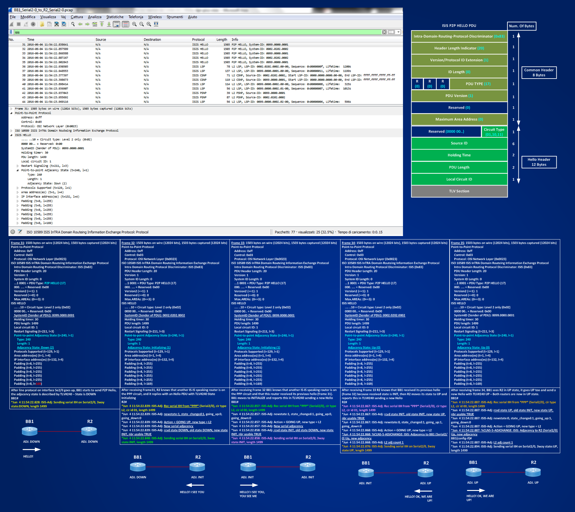
The P2P HELLO PDU has a shorter header (20 bytes) comparing it to the headers of LAN HELLO PDUs (27 bytes), also there is only one single type (17) for both L1 and L2 circuits. The handshaking is made possible by the exchange of TLV#240 Adjacency State that contains the status of the adjacency as seen by the system that is sending the PDU.
Now, looking carefully at the above picture someone may argue that what I wrote in sentence like “Hello, I see you, you see me” it’s not strictly correct, because in each P2P Hellos, that BB1 and R2 exchange, there is no field that can indicate to one router that the other router has seen it. In other words, we are missing a field, like TLV#6 in LAN HELLO, that brings the system-id of the neighboring router. Then, when a router receives an hello containing TLV#240 and sees that the state is changed, it ASSUMES that this change is caused by the Hello it sent at previous step. The assumption can be considered safe because the link is point-to-point and only two systems should be on the link, but there are scenario (read at the complete book if you wanna go further on this matter) where this assumption cannot be valid or scenario where the point-to-point link is realized with active L1 systems, in both such situations a router using the basic TLV#240 cannot be really sure if the change in the adjacency state is caused by an information it previously sent on the link and then it could change its status based on false assumptions. To overcome this limitations TLV#240 has been expanded from 1 byte to 15 bytes. IOS, by default, sends the basic 1 byte TLV#240 as I’ve seen before, JunOs sends always the 15 bytes version. In IOS the insertion of the 15-byte version can be controlled using a command:
BB1(config)#int se2/0
BB1(config-if)#isis three-way-handshake ?
cisco Cisco implementation of three-way handshake (default)
ietf IETF implementation of three-way handshake
<cr>
BB1(config-if)#isis three-way-handshake ietf
BB1(config-if)#shut
R2(config)#int se2/0
R2(config-if)#isis three-way-handshake ietf
R2(config-if)#shut
BB1(config)#int se2/0
BB1(config-if)#no shut
*Jun 5 14:23:44.562: %LINK-3-UPDOWN: Interface Serial2/0, changed state to up
*Jun 5 14:24:02.738: %LINEPROTO-5-UPDOWN: Line protocol on Interface Serial2/0, changed state to up
R2(config)#int se2/0
R2(config-if)#no shut
*Jun 5 14:24:02.711: %LINK-3-UPDOWN: Interface Serial2/0, changed state to up
*Jun 5 14:24:02.712: %LINEPROTO-5-UPDOWN: Line protocol on Interface Serial2/0, changed state to up
Debugging IS-IS adjacency:
BB1#
*Jun 5 14:24:03.809: ISIS-Adj: Sending serial IIH on Serial2/0, 3way state:DOWN, length 1499
*Jun 5 14:24:03.837: ISIS-Adj: Rec serial IIH from *PPP* (Serial2/0), cir type L2, cir id 00, length 1499
*Jun 5 14:24:03.837: ISIS-Adj: received Extended Circuit Number: 0x100
*Jun 5 14:24:03.837: ISIS-Adj: received Neighbor System-ID (must be our) 0099.0000.0001
*Jun 5 14:24:03.837: ISIS-Adj: received Neighbor ext.circuit ID (must be our) 0x101
*Jun 5 14:24:03.837: ISIS-Adj: newstate:1, state_changed:1, going_up:0, going_down:0
*Jun 5 14:24:03.837: ISIS-Adj: Action = GOING UP, new type = L2
*Jun 5 14:24:03.837: ISIS-Adj: New serial adjacency
*Jun 5 14:24:03.837: ISIS-Adj: rcvd state INIT, old state DOWN, new state INIT, nbr usable TRUE
*Jun 5 14:24:03.846: ISIS-Adj: Sending serial IIH on Serial2/0, 3way state:INIT, length 1499
*Jun 5 14:24:03.876: ISIS-Adj: Rec serial IIH from *PPP* (Serial2/0), cir type L2, cir id 00, length 1499
*Jun 5 14:24:03.876: ISIS-Adj: rcvd state UP, old state INIT, new state UP, nbr usable TRUE
*Jun 5 14:24:03.876: ISIS-Adj: received Extended Circuit Number: 0x100
*Jun 5 14:24:03.876: ISIS-Adj: received Neighbor System-ID (must be our) 0099.0000.0001
*Jun 5 14:24:03.876: ISIS-Adj: received Neighbor ext.circuit ID (must be our) 0x101
*Jun 5 14:24:03.876: ISIS-Adj: newstate:0, state_changed:1, going_up:1, going_down:0
*Jun 5 14:24:03.876: ISIS-Adj: Action = GOING UP, new type = L2
*Jun 5 14:24:03.876: %CLNS-5-ADJCHANGE: ISIS: Adjacency to R2 (Serial2/0) Up, new adjacency
*Jun 5 14:24:03.876: ISIS-Adj: L2 adj count 1
*Jun 5 14:24:03.885: ISIS-Adj: Sending serial IIH on Serial2/0, 3way state:UP, length 1499
R2#
*Jun 5 14:24:03.818: ISIS-Adj: Rec serial IIH from *PPP* (Serial2/0), cir type L2, cir id 01, length 1499
*Jun 5 14:24:03.818: ISIS-Adj: received Extended Circuit Number: 0x101
*Jun 5 14:24:03.818: ISIS-Adj: newstate:1, state_changed:1, going_up:0, going_down:0
*Jun 5 14:24:03.818: ISIS-Adj: Action = GOING UP, new type = L2
*Jun 5 14:24:03.818: ISIS-Adj: New serial adjacency
*Jun 5 14:24:03.818: ISIS-Adj: rcvd state DOWN, old state DOWN, new state INIT, nbr usable TRUE
*Jun 5 14:24:03.827: ISIS-Adj: Sending serial IIH on Serial2/0, 3way state:INIT, length 1499
*Jun 5 14:24:03.857: ISIS-Adj: Rec serial IIH from *PPP* (Serial2/0), cir type L2, cir id 01, length 1499
*Jun 5 14:24:03.857: ISIS-Adj: rcvd state INIT, old state INIT, new state UP, nbr usable TRUE
*Jun 5 14:24:03.857: ISIS-Adj: received Extended Circuit Number: 0x101
*Jun 5 14:24:03.857: ISIS-Adj: received Neighbor System-ID (must be our) 0002.0202.0002
*Jun 5 14:24:03.857: ISIS-Adj: received Neighbor ext.circuit ID (must be our) 0x100
*Jun 5 14:24:03.857: ISIS-Adj: newstate:0, state_changed:1, going_up:1, going_down:0
*Jun 5 14:24:03.857: ISIS-Adj: Action = GOING UP, new type = L2
*Jun 5 14:24:03.857: %CLNS-5-ADJCHANGE: ISIS: Adjacency to BB1 (Serial2/0) Up, new adjacency
*Jun 5 14:24:03.857: ISIS-Adj: L2 adj count 1
*Jun 5 14:24:03.867: ISIS-Adj: Sending serial IIH on Serial2/0, 3way state:UP, length 1499
Comparing these debugs with the previous ones it’s easy to see that the sequence of steps to form the adjacency are the same, the difference is in the following messages:
BB1#
*Jun 5 14:24:03.837: ISIS-Adj: received Neighbor System-ID (must be our) 0099.0000.0001
*Jun 5 14:24:03.837: ISIS-Adj: received Neighbor ext.circuit ID (must be our) 0x101
R2#
*Jun 5 14:24:03.857: ISIS-Adj: received Neighbor System-ID (must be our) 0002.0202.0002
*Jun 5 14:24:03.857: ISIS-Adj: received Neighbor ext.circuit ID (must be our) 0x100
These messages are relative to the expanded 15-byte version of TLV#240, below you can see the captured packets:
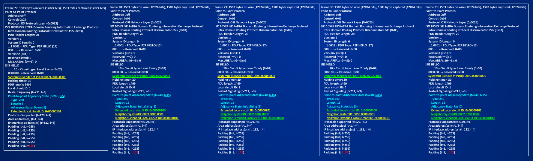
I can see that for the first Hello PDU sent by BB1, TLV#240 is expanded to 5 bytes length to include its Extended Circuit ID that expands from the old 1 bytes size to 4 bytes (This should help in taking account of more interface numbers, in IOS the Local Circuit ID is taken from the Interface Index, in JunOs for IS-IS it’s always kept to a constant value of 1, because this is only local information and it is never processed in IS-IS). After a router receives an Hello PDU from the router at the other side of the link, TLV#240 is expanded up to 15 bytes including its Extended Circuit ID (4 bytes) and Extended Circuit ID (4 bytes) and System-ID (6 bytes) received from the neighbors.
Now, I have all the elements to go back to the Pseudo-Node concept on LAN circuits. I learned so far that on LAN circuits, by default, a pseudo-node is created and inserted in the IS-IS databases to represent the LAN and have a more scalable protocol reducing the number of adjacency problem from N*N factor to a only N factor (with N the number of systems on the LAN). I know also that for Ethernet point-to-point circuit this pseudo-node representation adds only some overhead and no benefits, because we have only 2 routers on the link.
IOS give me the possibility to suppress the creation of a pseudo-node on P2P LAN CIRCUIT using this command under the involved interfaces:
“isis network point-to-point”
The magic of pseudo-node suppression is done inside this command using P2P HELLO PDU instead of LAN HELLO PDUs. Below you can find an example to see what happens, I will change link connected to e0/1 interfaces of BB1 and BB2 to a point-to-point network:
BB1(config)#int e0/1
BB1(config-if)#isis network point-to-point
BB1(config-if)#isis three-way-handshake ietf
BB2(config)#int e0/1
BB2(config-if)#isis network point-to-point
BB2(config-if)#isis three-way-handshake ietf
BB1#sh int e0/1 | i Hard
Hardware is AmdP2, address is aabb.cc00.0510 (bia aabb.cc00.0510)
BB2#sh int e0/1 | i Hard
Hardware is AmdP2, address is aabb.cc00.0610 (bia aabb.cc00.0610)
In the following picture you can see the captured P2P over LAN HELLO PDUs
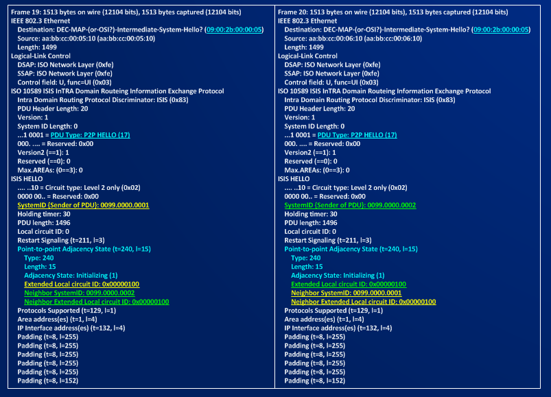
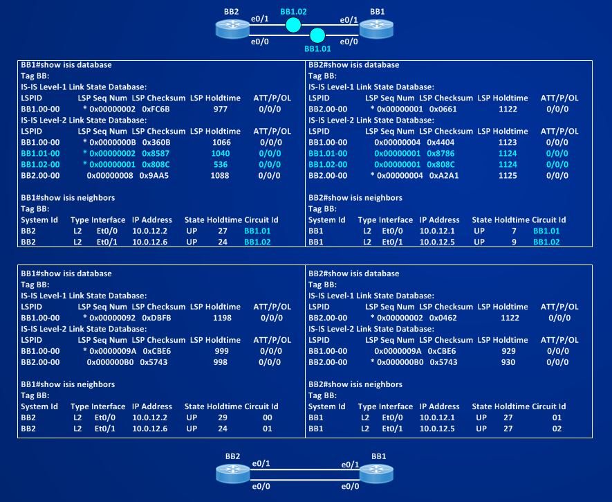
Picture shows clearly that P2P HELLO PDUS are simply encapsulated inside an ethernet frame and sent on the link. A difference with standard LAN HELLO PDUs is visible also in the Destination MAC Address of the frame, in this case set to 09:00:2b:00:00:05 ALL Intermediate Systems, HELLO L1 LAN PDUs are instead sent to ALL-L1-IS (01:80:C2:00:00:14) and HELLO L2 LAN PDUs are sent to All-L2-IS (01:80:C2:00:00:15). In the following picture you can compare the IS-IS databases in both cases, when using pseudo-nodes and when not using them. If you don’t use them on P2P-LAN you can have a cleaner and more concise database and you reduce overhead of the protocol.
It’s time to recap one more time what I learned so far:
A] IS-IS uses two types of link circuits – Broadcast Link (where a Designated-IS is elected) and Point-to-Point (P2P) Links.
B] IS-IS speaking routers exchange messages having a Common Header of 8 Bytes.
C] IS-IS uses HELLO PDUs to discover neighbors and implementing a keepalive mechanism to detect liveness of the adjacent systems, there are 3 TYPES of HELLO PDUs, L1 LAN HELLO (Code Type 15 DMAC 01:80:C2:00:00:14), L2 LAN HELLO (Code Type 16 DMAC 01:80:C2:00:00:15), P2P HELLO (Code Type 17).
D] IS-IS implements a 3-way handshaking mechanism to establish adjacency on both Broadcast and P2P Links. TLV#6 (IS Neighbor) works for this scope on Broadcast Link, TLV#240 (Adjacency State) works for this scope on P2P Links.
E] An extended version of 15 bytes of the TLV#240 can be used, configuring the interface command “isis three-way-handshake ietf”, to make more robust the 3-way handshake.
F] IS-IS builds two databases one for each logical level (LEVEL-1, LEVEL-2)
G] Each router is represented in the database by a LSP-ID that is an index to an entry in the database – LSP-ID = [SYSTEM_ID.PSEUDO_NODE_ID-FRAGMENT-ID] and by some informational elements called TLVs.
H] On Broadcast Links, by default, routers are neighbors with virtual nodes called PSEUDO-NODES, PSEUDO-NODEs are described in the database by a NOT-ZERO PSEUDO-NODE-ID and they inherit their SYSTEM-ID from the elected DIS on the LAN segments.
I] On P2P LAN circuit, the presence of the PSEUDO-NODE adds only overhead to the protocol, I can manually suppress the presence of the PSEUDO-NODE encapsulating a P2P HELLO PDU into an ethernet frame using the interface command “isis network point-to-point”, in this case the Adjacency State information is maintained by TLV#240 instead of TLV#6.
Then, now I know how IS-IS neighboring routers can discover each other on different link types and how they form and maintain adjacency, but how do they exchange the information contained in their databases in such a way that all routers of the network have a common view? This is argument of the next section.