In this article I will do some tests about MPLS TE while I’m reading the book “Traffic Engineering with MPLS”
Reading the book I found that to enable MPLS TE, like for any other networking stuff, you need to satisfy some prerequisites, they are:
• A release of the Cisco IOS Software that supports MPLS Traffic Engineering
• Cisco Express Forwarding (CEF) enabled in your network
• A link-state routing protocol (OSPF or IS-IS) as your Interior Gateway Protocol (IGP)
• Traffic engineering enabled globally on the router
• A loopback interface to use as your MPLS Traffic Engineering router ID (RID)
• Basic TE tunnel configuration
In the piece of the book I read so far I have not met a reference topology yet, so I will build mine. I will use IS-IS as IGP since I’m reviewing this IGP at the same time, this lets me makes some practice on IS-IS too.
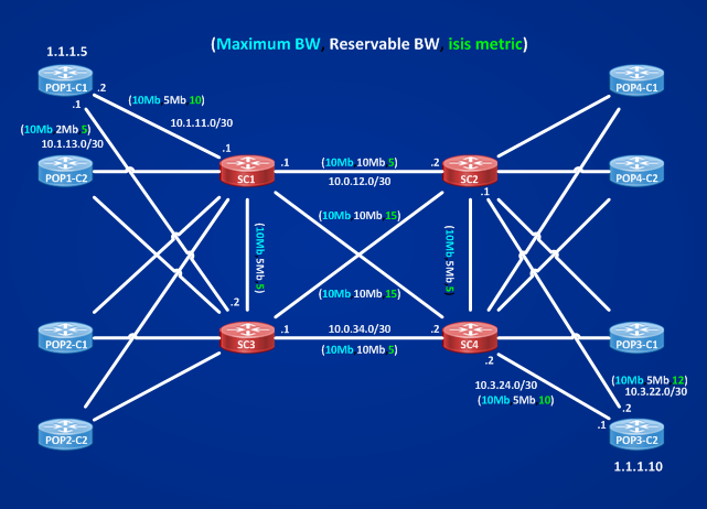
The definition I found in the book is “Traffic engineering is manipulating your traffic to fit your network”, using this definition lets me think that to move traffic from one path of the network to a different path I need to have more then one paths to distribute traffic, then I will use this topology:
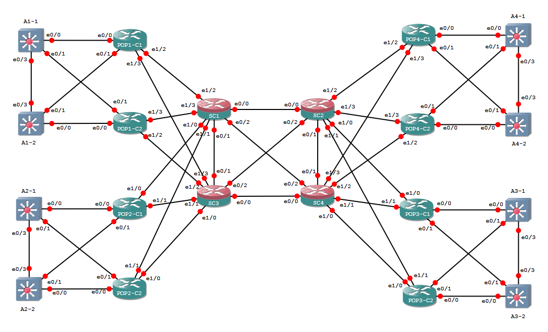
Four PoPs are connected to a SuperCore (SC1, SC2, SC3, SC4) of full meshed SuperRouters!
I configured six user VLANs on all couples of switches (Ax-1,2) in all for PoPs. I configured these users’s VLANs:
xy.xy.xy.0/24 where x=1,2,3,4 identifies the PoP, y=1,2,3,4,5,6 identifies the Vlan, for example in PoP 1 I have Vlan11,Vlan12,Vlan13,Vlan14,Vlan15,Vlan16, User’s VLANs are in HSRP where switch 1 (Ax-1) of the PoP is hsrp active for odd vlans and switch 2 (Ax-2) is hsrp active for even vlans:
A1-1#sh standby brief
P indicates configured to preempt.
|
Interface Grp Pri P State Active Standby Virtual IP
Vl11 11 150 P Active local 11.11.11.2 11.11.11.254
Vl12 12 100 Standby 12.12.12.2 local 12.12.12.254
Vl13 13 150 P Active local 13.13.13.2 13.13.13.254
Vl14 14 100 Standby 14.14.14.2 local 14.14.14.254
Vl15 15 150 P Active local 15.15.15.2 15.15.15.254
Vl16 16 100 Standby 16.16.16.2 local 16.16.16.254
A1-2#sh standby brief
P indicates configured to preempt.
|
Interface Grp Pri P State Active Standby Virtual IP
Vl11 11 100 Standby 11.11.11.1 local 11.11.11.254
Vl12 12 150 P Active local 12.12.12.1 12.12.12.254
Vl13 13 100 Standby 13.13.13.1 local 13.13.13.254
Vl14 14 150 P Active local 14.14.14.1 14.14.14.254
Vl15 15 100 Standby 15.15.15.1 local 15.15.15.254
Vl16 16 150 P Active local 16.16.16.1 16.16.16.254
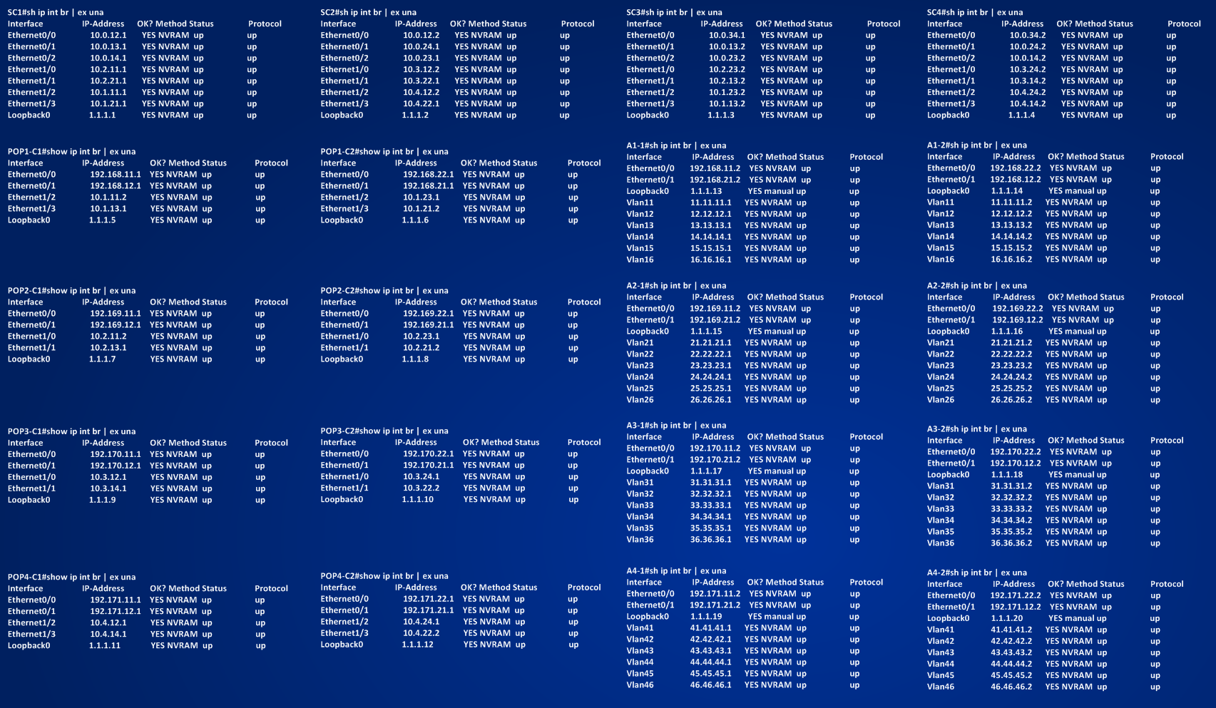
The following picture shows all the configured IP addresses.
 Below you can find some tests showing ip connectivity:
A1-1#ping 46.46.46.254 source 11.11.11.1 ==> Vlan11 (PoP 1) to Vlan46 (PoP 4) (VIP)
Type escape sequence to abort.
Sending 5, 100-byte ICMP Echos to 46.46.46.254, timeout is 2 seconds:
Packet sent with a source address of 11.11.11.1
!!!!!
Success rate is 100 percent (5/5), round-trip min/avg/max = 3/4/6 ms
A1-2#ping 36.36.36.254 source 16.16.16.2 ==> Vlan16 (PoP 1) to Vlan36 (PoP 3) (VIP)
Type escape sequence to abort.
Sending 5, 100-byte ICMP Echos to 36.36.36.254, timeout is 2 seconds:
Packet sent with a source address of 16.16.16.2
!!!!!
Success rate is 100 percent (5/5), round-trip min/avg/max = 5/5/8 ms
A2-2#ping 33.33.33.254 source 21.21.21.2 ==> Vlan21 (PoP 2) to Vlan33 (PoP 3) (VIP)
Type escape sequence to abort.
Sending 5, 100-byte ICMP Echos to 33.33.33.254, timeout is 2 seconds:
Packet sent with a source address of 21.21.21.2
!!!!!
Success rate is 100 percent (5/5), round-trip min/avg/max = 4/5/7 ms
A4-2#ping 23.23.23.254 source 44.44.44.2 ==> Vlan44 (PoP 4) to Vlan23 (PoP 2) (VIP)
Type escape sequence to abort.
Sending 5, 100-byte ICMP Echos to 23.23.23.254, timeout is 2 seconds:
Packet sent with a source address of 44.44.44.2
!!!!!
Success rate is 100 percent (5/5), round-trip min/avg/max = 3/5/6 ms
Here you can see the IS-IS topology I set up, nothing too complicated, core routers (SC1, SC2, SC3, SC4) are level-2 only routers, PoP routers POPx-C1,2 are level-1-2 routers and L3 switches inside each PoP are level-1 only devices.
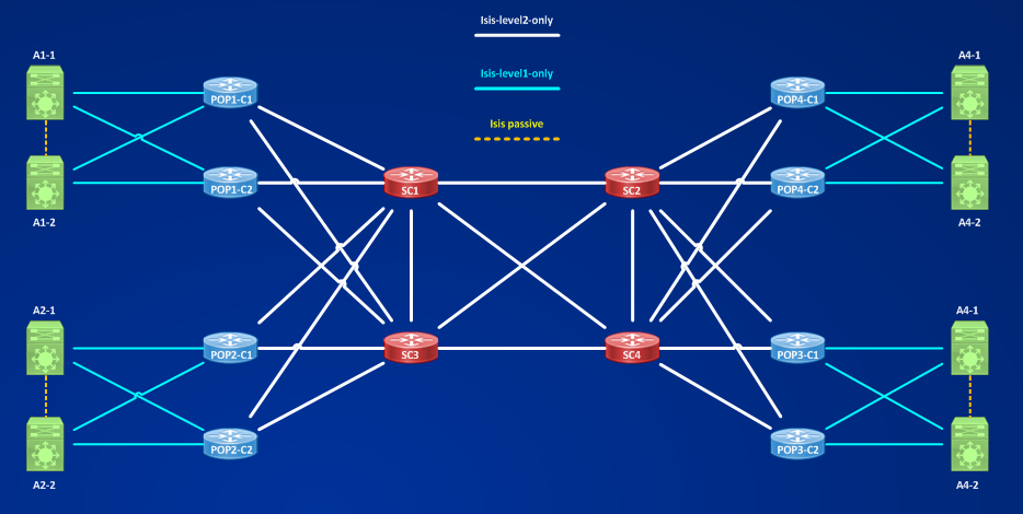
I redistributed level-2 into level-1 at each POPx-C1,2 using a prefix list that allows switch in each PoP Ax-y to be able to learn Loopback addresses and remote user’s vlans’ ip addresses, for example on POP1-C1 the prefix list is:
POP1-C1#sh run | s ip prefix
ip prefix-list ISIS-L2 seq 5 permit 1.1.1.0/24 ge 32
ip prefix-list ISIS-L2 seq 10 permit 21.21.21.0/24
ip prefix-list ISIS-L2 seq 15 permit 22.22.22.0/24
ip prefix-list ISIS-L2 seq 20 permit 23.23.23.0/24
ip prefix-list ISIS-L2 seq 25 permit 24.24.24.0/24
ip prefix-list ISIS-L2 seq 30 permit 25.25.25.0/24
ip prefix-list ISIS-L2 seq 35 permit 26.26.26.0/24
ip prefix-list ISIS-L2 seq 40 permit 31.31.31.0/24
ip prefix-list ISIS-L2 seq 45 permit 32.32.32.0/24
ip prefix-list ISIS-L2 seq 50 permit 33.33.33.0/24
ip prefix-list ISIS-L2 seq 55 permit 34.34.34.0/24
ip prefix-list ISIS-L2 seq 60 permit 35.35.35.0/24
ip prefix-list ISIS-L2 seq 65 permit 36.36.36.0/24
ip prefix-list ISIS-L2 seq 70 permit 41.41.41.0/24
ip prefix-list ISIS-L2 seq 75 permit 42.42.42.0/24
ip prefix-list ISIS-L2 seq 80 permit 43.43.43.0/24
ip prefix-list ISIS-L2 seq 85 permit 44.44.44.0/24
ip prefix-list ISIS-L2 seq 90 permit 45.45.45.0/24
ip prefix-list ISIS-L2 seq 95 permit 46.46.46.0/24
POP1-C1#sh run | s route-map
route-map LVL2-TO-LVL1 permit 10
match ip address prefix-list ISIS-L2
POP1-C1#sh run | s r i
router isis CORE
mpls ldp autoconfig level-2
net 49.0001.0001.0015.00
log-adjacency-changes
redistribute isis ip level-2 into level-1 route-map LVL2-TO-LVL1
Here you can download config for all devices:
Now that my testing network is ready, I have to start building Traffic Engineering Tunnels that once active I will use to forward the traffic down to.
STEP 1] – enabling globally MPLS Traffic Engineering ==> the command is “mpls traffic-eng tunnels“. The command should be applied on all routers that are involved in building the tunnel, in my example routers are POPx-C1,2 and SC1,SC2,SC3,SC4
STEP 2] – every interfaces that touches a TE tunnel must be configured for MPLS TE, the command is the same of STEP1 and must be set under involved interfaces. For example:
POP1-C1#sh run int e1/2 | b interface
interface Ethernet1/2
ip address 10.1.11.2 255.255.255.252
ip router isis CORE
mpls traffic-eng tunnels
POP1-C1#sh run int e1/3 | b interface
interface Ethernet1/3
ip address 10.1.13.1 255.255.255.252
ip router isis CORE
mpls traffic-eng tunnels
POP1-C1#show mpls traffic-eng tunnels summary
Signalling Summary:
LSP Tunnels Process: running
Passive LSP Listener: running
RSVP Process: running
Forwarding: enabled
Head: 0 interfaces, 0 active signalling attempts, 0 established
0 activations, 0 deactivations
0 SSO recovery attempts, 0 SSO recovered
Midpoints: 0, Tails: 0
Periodic reoptimization: every 3600 seconds, next in 2575 seconds
Periodic FRR Promotion: Not Running
Periodic auto-bw collection: every 300 seconds, next in 175 seconds
POP1-C1#show mpls interfaces ==> Note the YES under Tunnel column.
Interface IP Tunnel BGP Static Operational
Ethernet1/2 Yes (ldp) Yes No No Yes
Ethernet1/3 Yes (ldp) Yes No No Yes
STEP 3] – TE Tunnels are represented as Tunnel interfaces on routers, so I need to configure a basic Tunnel interface. In this first example I will set up a Tunnel1132 starting at router POP1-C1 (HEADEND) to router POP3-C2 (TAILEND) (number logic is: first POP (1),first router (1)=11 to third PoP (3), second router (2) ==> Tunnel number is 1132)
POP1-C1#sh run int Tu1132 | b interface
interface Tunnel1132
ip unnumbered Loopback0
tunnel mode mpls traffic-eng
tunnel destination 1.1.1.10
tunnel mpls traffic-eng path-option 10 dynamic
no routing dynamic ==> configured by default IOS 15.4(1)T
POP1-C1#show int Tu1132
Tunnel1132 is up, line protocol is down
Hardware is Tunnel
Interface is unnumbered. Using address of Loopback0 (1.1.1.5)
MTU 17936 bytes, BW 100 Kbit/sec, DLY 50000 usec,
reliability 255/255, txload 1/255, rxload 1/255
Encapsulation TUNNEL, loopback not set
Keepalive not set
Tunnel source 1.1.1.5, destination 1.1.1.10
Tunnel protocol/transport Label Switching
Tunnel transmit bandwidth 8000 (kbps)
Tunnel receive bandwidth 8000 (kbps)
Last input never, output never, output hang never
Last clearing of “show interface” counters 00:04:25
Input queue: 0/75/0/0 (size/max/drops/flushes); Total output drops: 0
Queueing strategy: fifo
Output queue: 0/0 (size/max)
5 minute input rate 0 bits/sec, 0 packets/sec
5 minute output rate 0 bits/sec, 0 packets/sec
0 packets input, 0 bytes, 0 no buffer
Received 0 broadcasts (0 IP multicasts)
0 runts, 0 giants, 0 throttles
0 input errors, 0 CRC, 0 frame, 0 overrun, 0 ignored, 0 abort
0 packets output, 0 bytes, 0 underruns
0 output errors, 0 collisions, 0 interface resets
0 unknown protocol drops
0 output buffer failures, 0 output buffers swapped out
Tunnel1132 is down because I have to complete the configuration. Before moving on completing the needed configuration to tear up the TE Tunnel, I need to clarify to myself:
What MPLS TE is used for? Reading the book “Traffic Engineering with MPLS” at page 16 I found good answers:
a) Optimizing your network utilization
b) Handling unexpected congestion
c) Handling link and node failures
All these three things have to do with “I wanna force traffic to follow a path that is different by the path traffic should follow as established by my IGP”, also case c) falls into this category, for example when you want move traffic quickly from one path to another after a link failure before normal IGP convergence happens (MPLS TE Fast Reroute).
To make possible moving the traffic between TE Tunnels, I have to distribute relevant information into the newtork, main information could be:
### AVAILABLE BANDWIDTH PER INTERFACE PER PRIORITY###
### ATTRIBUTE FLAGS PER INTERFACE ###
### ADMINISTRATIVE WEIGHT PER INTERFACE ###
You know about bandwidth, priority it’s a mean to give one tunnel better importance than another one in reserving bandwidth on a specific interface. Administrative weight is the cost.
But, who is distributing this information in the network?
MPLS TE USES THE IGP TO DISTRIBUTE INFORMATION ABOUT AVAILABLE RESOURCES IN THE NETWORK. In my example the IGP is IS-IS.
Configure the IGP to support MPLS TE is rather simple, understanding what exactly happens under the protocol is not so simple, to do that read the whole book “Traffic Engineering with MPLS” or other resources.
When using IS-IS as IGP to distribute MPLS TE information the necessary step is:
(o) Enabling WIDE METRIC support
Normally ISIS cost for a link is 10:
POP1-C1#show clns interface e1/2 | i Metric
Level-1 Metric: 10, Priority: 64, Circuit ID: POP1-C1.03
Level-1 IPv6 Metric: 10
Level-2 Metric: 10, Priority: 64, Circuit ID: POP1-C1.03
Level-2 IPv6 Metric: 10
In old IOS the is-is metric was a 6 bit quantity (0 – 63 values) and the total cost of the path was 1023. Newer IOS has isis metric updated to a wide setting:
POP1-C1(config)#int e1/2
POP1-C1(config-if)#isis metric ?
<1-16777214> Default metric ==> 24 bit metric
maximum Maximum metric. All routers will exclude this link from their SPF
The maximum configurable isis metric for a link is 16777214 2^24 – 2, this because 16777215 matches the “maximum” keyword. The wide metric per link is enabled in newer IOS and the isis sub TLV describing it is the type 135 TLV (IP-extended-TLVs). TLV 135 is not specific to MPLS TE using IS-IS but it is used with other MPLS enhancement to support MPLS TE.
With IOS I’m using (15.4(1)T) the isis process doesn’t support by default wide metric, this can be verified by using the command:
POP1-C1#show clns protocol
IS-IS Router: CORE
System Id: 0001.0001.0015.00 IS-Type: level-1-2
Manual area address(es):
49
Routing for area address(es):
49
Interfaces supported by IS-IS:
Ethernet1/3 – IP
Ethernet1/2 – IP
Ethernet0/1 – IP
Ethernet0/0 – IP
Loopback0 – IP
Redistribute:
static (on by default)
Distance for L2 CLNS routes: 110
RRR level: none
Generate narrow metrics: level-1-2
Accept narrow metrics: level-1-2
Generate wide metrics: none
Accept wide metrics: none
You can see that in the last two rows of the output IOS is not accepting and generating wide metric, so we need to configure the process to do it.
NOTE: many isis commands use the keyword “clns” instead of isis because isis extension to support IP protocol came later of the original ISO implementation, it’s an historical stuff (In other more recent OS, for example JunOS you don’t see clns because JunOS born after (I should verify this) Integrated IS-IS, then they choose wisely to not confuse networking people).
POP1-C1(config)#router isis CORE
POP1-C1(config-router)#mpls traffic-eng router-id Loopback 0
POP1-C1(config-router)#mpls traffic-eng level-2 ?
<cr>
POP1-C1(config-router)#mpls traffic-eng level-2
%Must enable wide metrics on level-2 first ==> MPLS TE support doesn’t work without wide metric support.
POP1-C1(config-router)#metric-style ?
narrow Use old style of TLVs with narrow metric
transition Send and accept both styles of TLVs during transition
wide Use new style of TLVs to carry wider metric
POP1-C1(config-router)#metric-style wide ?
level-1 Level-1 only
level-1-2 Level-1-2
level-2 Level-2 only
transition Accept both styles of TLVs during transition
<cr>
POP1-C1(config-router)#metric-style wide
POP1-C1(config-router)#mpls traffic-eng level-2
POP1-C1#sh run | s r i
router isis CORE
mpls ldp autoconfig level-2
mpls traffic-eng router-id Loopback0
mpls traffic-eng level-2 ==> tipically MPLS TE support spans only one level (as in OSPF spans only one area, tipically area0) but it could be configured as inter-level too.
net 49.0001.0001.0015.00
metric-style wide
log-adjacency-changes
redistribute isis ip level-2 into level-1 route-map LVL2-TO-LVL1
NOTE: if routers are already isis neighbors, when you change the metric style neighborship will be broken until all routers agree with the metric style configured. IOS supports three different metric style, there different combinations of metric style that lets MPLS TE works, but this should be on only during migration phase or something like this. At the end all routers must converge to support only wide metric for MPLS TE. Remember also to configure wide metric on all isis speaking routers, on those will never be a TE Headend or Tailend too, because if on one side you have narrow metric and on the other side wide metric, routers might become neighbors but they are unable to exchange isis routes.
POP1-C1#show clns protocol
IS-IS Router: CORE
System Id: 0001.0001.0015.00 IS-Type: level-1-2
Manual area address(es):
49
Routing for area address(es):
49
Interfaces supported by IS-IS:
Ethernet1/3 – IP
Ethernet1/2 – IP
Ethernet0/1 – IP
Ethernet0/0 – IP
Loopback0 – IP
Redistribute:
static (on by default)
Distance for L2 CLNS routes: 110
RRR level: level-2
Generate narrow metrics: none
Accept narrow metrics: none
Generate wide metrics: level-1-2
Accept wide metrics: level-1-2
After enabling wide metric and isis support on all routers the configured tunnel comes up:
*Jan 27 13:47:00.007: %LINEPROTO-5-UPDOWN: Line protocol on Interface Tunnel1132, changed state to up
POP1-C1#sh run int Tu1132 | b interface
interface Tunnel1132
ip unnumbered Loopback0
tunnel mode mpls traffic-eng
tunnel destination 1.1.1.10
tunnel mpls traffic-eng path-option 10 dynamic
no routing dynamic
POP1-C1#sh int Tu1132 | i up
Tunnel1132 is up, line protocol is up
NOTE: I have not configured bandwidth reservation or other traffic-eng parameters but Tunnel1132, once all routers have their IGP configured to support MPLS TE, comes up.
The following picture shows which is the established path:
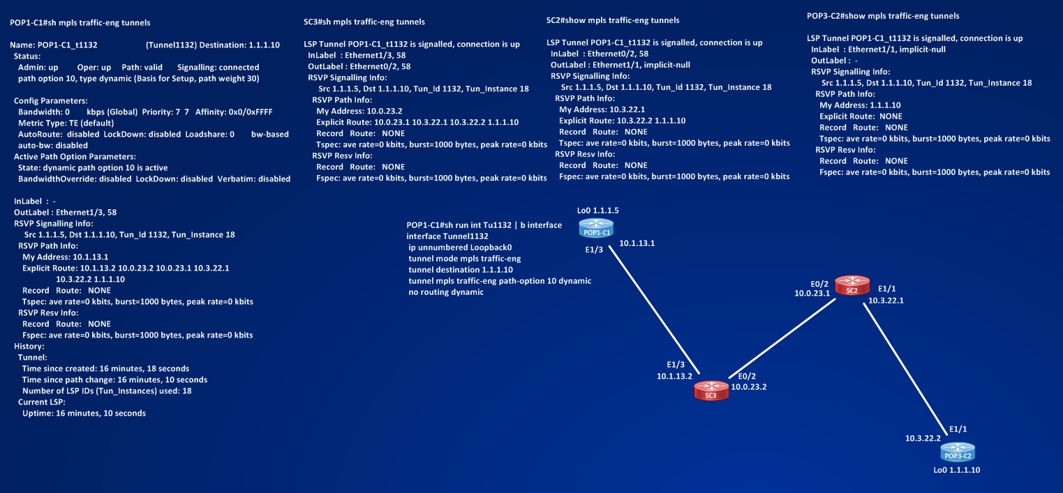 Looking at the picture above I can see that one path is built: POP1-C1 ==> SC3 ==> SC2 ==> POP3-C2. The command “show mpls traffic-eng tunnels” gives me a lot of information:
POP1-C1#show mpls traffic-eng tunnels
Name: POP1-C1_t1132 (Tunnel1132) Destination: 1.1.1.10
Status:
Admin: up Oper: up Path: valid Signalling: connected
path option 10, type dynamic (Basis for Setup, path weight 30)
Config Parameters:
Bandwidth: 0 kbps (Global) Priority: 7 7 Affinity: 0x0/0xFFFF
Metric Type: TE (default)
AutoRoute: disabled LockDown: disabled Loadshare: 0 bw-based
auto-bw: disabled
Active Path Option Parameters:
State: dynamic path option 10 is active
BandwidthOverride: disabled LockDown: disabled Verbatim: disabled
InLabel : –
OutLabel : Ethernet1/3, 58
RSVP Signalling Info:
Src 1.1.1.5, Dst 1.1.1.10, Tun_Id 1132, Tun_Instance 18
RSVP Path Info:
My Address: 10.1.13.1
Explicit Route: 10.1.13.2 10.0.23.2 10.0.23.1 10.3.22.1
10.3.22.2 1.1.1.10
Record Route: NONE
Tspec: ave rate=0 kbits, burst=1000 bytes, peak rate=0 kbits
RSVP Resv Info:
Record Route: NONE
Fspec: ave rate=0 kbits, burst=1000 bytes, peak rate=0 kbits
History:
Tunnel:
Time since created: 8 minutes, 28 seconds
Time since path change: 8 minutes, 20 seconds
Number of LSP IDs (Tun_Instances) used: 18
Current LSP:
Uptime: 8 minutes, 20 seconds
I can read the output as divided into 2 sections, the first section refers to configured (or taken by default or calculated some way) Tunnel parameters:
– Admin Status (UP), Operational Status (UP), Status of the built path (Valid), status of the signalling (connected)
– path option: type of tunnel (dynamic), 10 is a sort of preference index, lower numbers are preferred in order, you can specify two methods to bulid the path:
POP1-C1(config-if)#tunnel mpls traffic-eng path-option ?
<1-1000> preference for this path option
protect a path protection setup option
POP1-C1(config-if)#tunnel mpls traffic-eng path-option 15 ?
dynamic setup based on dynamically calculcated path
explicit setup based on preconfigured path ==> here you set a manual TE tunnel expliciting the routers you want in the path.
– path weight ==> the total cost of the path, here is 30 = 10 + 10 + 10 result of adding the IGP cost of the link that form the path.
By default Traffic-eng cost of a link = IGP cost of a link. In few cases, for example when a link brings a TE tunnel but it is not used only by TE but also for normal IP connectivity, there could be the necessity of setting to different values the two costs. The command to set the TE cost is:
POP1-C1(config)#interface e1/2
POP1-C1(config-if)#mpls traffic-eng administrative-weight ?
<0-4294967295> Weight
– Config Parameters:
Bandwidth = 0 Kbps ==> this is the Bandwidth the Tunnel is asking the network for. Why is 0? Because in the Tunnel1132 I have not configured yet this command:
POP1-C1(config)#int Tunnel1132
POP1-C1(config-if)#tunnel mpls traffic-eng bandwidth ?
<0-4294967295> bandwidth requirement in kbps
sub-pool tunnel uses sub-pool bandwidth
Priority: 7 7 ==> we have two types of priority, first value is the SETUP PRIORITY, second value is the HOLDING PRIORITY. Values go from 0 (the best) to 7 (the worst). Normally these values matches. Priority is used to assign a preference to tunnels and to decide which tunnel is more important than another one, when both tunnels are contending for the same resources (aka link bandwidth). The setup priority is the priority that the tunnels have when are establishing, the holding priority is the priority they have once are established. If a tunnel with better priority (lower value) asks for resources already assigned to another tunnel, the best tunnel push out the worst one. Playing with setup and holding priority gives me the possibility to create tunnels that for example never preempts other tunnels (setup priority 7) but once established cannot be pushed out (holding priority 0). You can set the priority using the command:
POP1-C1(config)#int Tunnel1132
POP1-C1(config-if)#tunnel mpls traffic-eng priority ?
<0-7> setup priority
POP1-C1(config-if)#tunnel mpls traffic-eng priority 7 ?
<0-7> hold priority
<cr>
POP1-C1(config-if)#tunnel mpls traffic-eng priority 7 7 ?
<cr>
7 is the default value for setup and holding priority.
– Affinity: 0x0/0xFFFF ==> These are attributes of the tunnel that can match link attributes flags:
POP1-C1(config)#int Tunnel1132
POP1-C1(config-if)#tunnel mpls traffic-eng affinity ?
<0x0-0xFFFFFFFF> affinity value
POP1-C1(config-if)#tunnel mpls traffic-eng affinity 0x1 ?
mask mask on desired link attributes
<cr>
POP1-C1(config-if)#tunnel mpls traffic-eng affinity 0x1 mas
POP1-C1(config-if)#tunnel mpls traffic-eng affinity 0x1 mask ?
<0x0-0xFFFFFFFF> affinity mask value
POP1-C1(config-if)#tunnel mpls traffic-eng affinity 0x1 mask 0x1 ?
<cr>
Affinity can be considered as a way to mark the tunnel with some flags making it feasible to be built on links with attributes flags matching the affinity of the tunnel. In more simple words it’s a way to say “Tunnel should cross only links in the networks that have these characteristics”. Characteristics on the link are 32 bit flags that can be set up with the command:
POP1-C1(config)#int e1/2
POP1-C1(config-if)#mpls traffic-eng attribute-flags ?
<0x0-0xFFFFFFFF> Attribute flags
POP1-C1(config-if)#mpls traffic-eng attribute-flags 0x1 ?
<cr>
I will do an example later.
– Labels: I see IN Label = N/A , OUT Label = Ethernet1/3, 58 – Why we have Labels? Because MPLS TE is an MPLS application, the signalled Label is the label sent into the network starting from the tail-end router in response to a PATH RSVP MESSAGE:
SC3#show mpls traffic-eng tunnels role middle | i Label
InLabel : Ethernet1/3, 58
OutLabel : Ethernet0/2, 58
SC2#show mpls traffic-eng tunnels role middle | i Label
InLabel : Ethernet0/2, 58
OutLabel : Ethernet1/1, implicit-null
POP3-C2#show mpls traffic-eng tunnels role tail | i Label
InLabel : Ethernet1/1, implicit-null
OutLabel : –
SC3 and SC2 are the middle router in the path, SC2 is the penultimate-hop router toward the tail of the tunnel, the tail-end signals an implicit-null (value 3) to SC2 (see below for details), then at each node a mapping is done between the TUNNEL and a label.
After the label info I can read in the output some RSVP information, from where does RSVP comes out? I have not configured RSVP.
It can be easily seen that to form a tunnel, thouhg a partial one, many things and protocols are behind the scene of a simple configuration:
1 – enable globally MPLS TE and on every interfaces that could be touched by a TE Tunnel.
2 – configure Tunnel interface with traffic-eng mode
3 – configure IGP to support MPLS TE (use wide metric if using IS-IS)
4 – routers builds a LSP path to support the Tunnel
5 – RSVP signals many info in some way
Then, let’s try to have a clearer idea. I completed step 1, and step 3, completed partially step 2, about step 4 and 5 something automatic (but configurable) happens.
About step 2: the configured Tunnel interface is:
POP1-C1#sh run int Tu1132 | b interface
interface Tunnel1132
ip unnumbered Loopback0
tunnel mode mpls traffic-eng
tunnel destination 1.1.1.10
tunnel mpls traffic-eng path-option 10 dynamic
no routing dynamic
One essential piece of information is missing ==> How much bandwidth do I want for this Tunnel? Let’s suppose we want 50 Mb of BW.
POP1-C1(config)#int Tu1132
POP1-C1(config-if)#tunnel mpls traffic-eng bandwidth 50000
How does POP1-C1 know which is the best path that respects the requested requirement (BW in this case) to go from Headend to the Tailend among all possible paths? To make this decision the Headend Router must have a view of the entire topology and how network resources are distributed in this topology. For example if we need 50 Mb of bandwidth, all links that the Tunnel will cross must have at least 50 Mb of reservable bandwidth.
But how we reserve bandwidth on a link? To reserve bandwidth on a single link we use RSVP protocol. The command is:
POP1-C1(config)#int e1/2
POP1-C1(config-if)#ip rsvp bandwidth ?
<1-10000000> Reservable Bandwidth (kbps)
ingress RSVP Ingress Reservable Bandwidth (kbps)
percent Specify a percentage of interface bandwidth
<cr>
POP1-C1(config-if)#ip rsvp bandwidth ==> not specifying kbps doesn’t mean we are reserving 0 Kbps, but we are reserving the 75% of the physical BW of the interface.
THIS COMMAND MUST BE ENABLED ON ALL INTERFACES THAT MUST BE CROSSED BY AN MPLS TE TUNNEL. Once the command is configured on over all the network, the headend router can know how reservable BW is distributed among all links of the network. Again who is distributing this information? Is the IGP extended to support MPLS TE that distributes this information.
IS-IS encodes MPLS TE information in an Extended IS reachability TLV, TLV TYPE 22, information distributed are:
ATTRIBUTE FLAGS:
Sub TLV id = 3, Size = 4 bytes, Definition = 32-bit bitmask that puts the link in one or more administrative groups – Interface Configuration Command = mpls traffic-eng attribute-flags
IPV4 INTERFACE ADDRESS:
Sub TLV id = 6, Size = 4 bytes, Definition = Interface mask is in the Type-22 TLV
Interface Configuration Command = ip address netmask
IPV4 NEIGHBOR ADDRESS:
Sub TLV id = 8, Size = 4 bytes, Definition = IP address of a neighbor on a p2p link; 0.0.0.0 if describing a broadcast link – Interface Configuration Command = NONE
MAXIMUM LINK BANDWIDTH:
Sub TLV id = 9, Size = 4 bytes, Definition = Maximum physical bandwidth on the interface, as seen in sh int and optionally set with the bandwidth command – Interface Configuration Command = bandwidth X (kbps)
MAXIMUM RESERVABLE BANDWIDTH:
Sub TLV id = 10, Size = 4 bytes, Definition = Amount of bandwidth that can be reserved on the link
Interface Configuration Command = ip rsvp bandwidth X (kbps)
UNRESERVED BANDWIDTH (PER PRIORITY LEVEL):
Sub TLV id = 11, Size = 32 bytes, Definition = For each priority level, the difference between the maximum reservable bandwidth and the reserved bandwidth per priority
Interface Configuration Command = NONE
TRAFFIC ENGINEERING METRIC:
Sub TLV id = 18, Size = 3 bytes, Definition = The IS-IS cost of the link, or a cost assigned by the TE code – Interface Configuration Command = isis metric or mpls traffic-eng administrativeweight
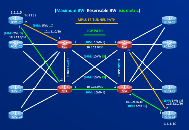
Once IGP has distributed this information, Headend router can have a topology view of the network and calculate the path it will take to reach the Tailend. To understand this I remove the configured Tu1132 and I complete configuration of the routers with ip rsvp bandwidth information, making possible bandwidth reservations different on some links. Picture below shows the scenario:
 I configured different reservable BW on each link and I changed the isis cost of the possible crossed links between POP1-C1 and POP3-C2. I have not reconfigured Tunnel1132 yet, let’s see which is the IGP path to the destination 1.1.1.10.
POP1-C1#traceroute 1.1.1.10 so 1.1.1.5
Type escape sequence to abort.
Tracing the route to 1.1.1.10
VRF info: (vrf in name/id, vrf out name/id)
1 10.1.13.2 [MPLS: Label 25 Exp 0] 2 msec 1 msec 1 msec
2 10.0.34.2 [MPLS: Label 17 Exp 0] 0 msec 1 msec 1 msec
3 10.3.24.1 0 msec 1 msec 0 msec
IGP path is the result of the Shortest Path First (SPF) algorithm applied to the isis database based only on metric of each link.
Then the path is POP1-C1 ==> SC3 ==> SC4 ==> POP3-C2
####### NOTE #######
The total IGP cost to 1.1.1.10 from POP1-C1 is 30:
POP1-C1#show ip route 1.1.1.10
Routing entry for 1.1.1.10/32
Known via “isis”, distance 115, metric 30, type level-2
Redistributing via isis CORE
Last update from 10.1.13.2 on Ethernet1/3, 01:10:05 ago
Routing Descriptor Blocks:
* 10.1.13.2, from 1.1.1.10, 01:10:05 ago, via Ethernet1/3
Route metric is 30, traffic share count is 1
This is the result of: POP1-C1 <= 5 => SC3 <= 5 => SC4 <= 10 => POP3-C2 <= 10 => Lo0 (1.1.1.10), this happens because isis adds loopback interface with a default metric of 10 to its database:
POP3-C2#sh isis database l2 detail ip unicast topology base POP3-C2.00-00 | i 1.1.1.10
Router ID: 1.1.1.10
IP Address: 1.1.1.10
Metric: 10 IP 1.1.1.10/32
POP3-C2#sh isis database l1 detail ip unicast topology base POP3-C2.00-00 | i 1.1.1.10
IP Address: 1.1.1.10
Metric: 10 IP 1.1.1.10/32
####### END NOTE #######
Now, let’s suppose I want to recreate Tunnel1132 from POP1-C1 to POP3-C2 and that this tunnel asks the network to reserve 3Mb/sec of bandwidth. Tunnel interface will be:
POP1-C1(config)#int Tu1132
*Jan 29 09:34:09.949: %LINEPROTO-5-UPDOWN: Line protocol on Interface Tunnel1132, changed state to down
POP1-C1(config-if)#ip unnumbered Lo0
POP1-C1(config-if)#tunnel mode mpls traffic-eng
POP1-C1(config-if)#tunnel destination 1.1.1.10
POP1-C1(config-if)#tunnel mpls traffic-eng bandwidth 3000
POP1-C1(config-if)#tunnel mpls traffic-eng priority 7 7
POP1-C1(config-if)#tunnel mpls traffic-eng path-option 10 dynamic
*Jan 29 09:39:03.379: %LINEPROTO-5-UPDOWN: Line protocol on Interface Tunnel1132, changed state to up
Let’s see which TE path has been built by POP1-C1:
POP1-C1#show mpls traffic-eng tunnels Tunnel 1132
Name: POP1-C1_t1132 (Tunnel1132) Destination: 1.1.1.10
Status:
Admin: up Oper: up Path: valid Signalling: connected
path option 10, type dynamic (Basis for Setup, path weight 27)
Config Parameters:
Bandwidth: 3000 kbps (Global) Priority: 7 7 Affinity: 0x0/0xFFFF
Metric Type: TE (default)
AutoRoute: disabled LockDown: disabled Loadshare: 3000 bw-based
auto-bw: disabled
Active Path Option Parameters:
State: dynamic path option 10 is active
BandwidthOverride: disabled LockDown: disabled Verbatim: disabled
InLabel : –
OutLabel : Ethernet1/2, 58
RSVP Signalling Info:
Src 1.1.1.5, Dst 1.1.1.10, Tun_Id 1132, Tun_Instance 1
RSVP Path Info:
My Address: 10.1.11.2
Explicit Route: 10.1.11.1 10.0.12.1 10.0.12.2 10.3.22.1
10.3.22.2 1.1.1.10
Record Route: NONE
Tspec: ave rate=3000 kbits, burst=1000 bytes, peak rate=3000 kbits
RSVP Resv Info:
Record Route: NONE
Fspec: ave rate=3000 kbits, burst=1000 bytes, peak rate=3000 kbits
Shortest Unconstrained Path Info:
Path Weight: 20 (TE)
Explicit Route: 10.1.13.1 10.1.13.2 10.0.34.1 10.0.34.2
10.3.24.2 10.3.24.1 1.1.1.10
History:
Tunnel:
Time since created: 16 minutes, 50 seconds
Time since path change: 13 minutes, 55 seconds
Number of LSP IDs (Tun_Instances) used: 1
Current LSP:
Uptime: 13 minutes, 55 seconds
In the first section of the output I see configured tunnel parameters: Requested BW = 3Mb/sec, Priority (Setup=7, Hold=7), affinity=0x0 (not configured).
In the second section about RSVP info I can read in the Explicit Route Object (ERO) the path calculated by POP1-C1:
RSVP Path Info:
My Address: 10.1.11.2
Explicit Route: 10.1.11.1 10.0.12.1 10.0.12.2 10.3.22.1
10.3.22.2 1.1.1.10
The path then is: POP1-C1 ==> SC1 ==> SC2 ==> POP3-C2
I can read another interesting information too:
Shortest Unconstrained Path Info:
Path Weight: 20 (TE)
Explicit Route: 10.1.13.1 10.1.13.2 10.0.34.1 10.0.34.2
10.3.24.2 10.3.24.1 1.1.1.10
This unconstrained path is: POP1-C1 ==> SC3 ==> SC4 ==> POP3-C2 and matches exactly the IGP calculated path based only on IGP metric.
It’s worth to notice that the Shortest Unconstrained Path has a better cost (20) than the CSPF path (27) to the tunnel tail.
From this little example should be clear that to realize this step:
4 – routers builds a LSP path to support the Tunnel
Routers execute a more detailed version of the Shortest Path First ==> The Constrained Shortest Path First (CSPF), this second algorithm can be considered more detailed because it is executed on a topology database where each link have many properties and not only the IGP metric of the link, these other properties are the seven parameters reported above and flooded by the IGP (isis in this case).
In this case why the two paths are different? Reason is that the reservable bandwidth on the link between POP1-C1 and SC3 is only 2Mb so it cannot satisfy the bandwidth requirement Tunnel1132 is asking for, then the other link POP1-C1 to SC1 is on the path. From SC1 to the destination all possible links satisfy the BW requirement, then the calculation is completed based on IGP metric.
POP1-C1#show mpls traffic-eng tunnels Tunnel 1132 | i path weight
path option 10, type dynamic (Basis for Setup, path weight 27) ==> the total cost of the calculated path is 27 (10 + 5 + 12)
When calculating CSPF, if some paths tie, the tiebreaker are:
1] Take the path with the largest minimum available bandwidth.
2] If there is still a tie, take the path with the lowest hop count (the number of routers in the path).
3] If there is still a tie, take the path that is the first listed in your software implementation of the CSPF code.
To complete the puzzle about how an MPLS TE Tunnel is built I still miss one piece, I know so far that when an Headend Router wants to build an MPLS TE Tunnel with some characterstics (bandwidth, affinity … ) it calculates the CSPF algorithm on a local topology view of the network constrained by the characteristics it wants to impose on the path built for the tunnel. These furhter characteristics are flooded by the IGP.
But how do other routers know that the Headend Router wants to build this path crossing them? The headend routers must SIGNAL the presence of the Tunnel it wants to build. This job of setup and maintenance and error signalling of the Tunnel is done by the RSVP protocol.
I don’t want here enter the details of RSVP because you can read brick-book about the protocol or even better you can read the RFC 2205, what I want to do is give an idea of the RSVP messages exchanged by routers to establish the MPLS TE path.
RSVP Messages in Cisco IOS are of 9 different types (reference “Traffic engineering with MPLS” ):
1] PATH MESSAGE ==> Used to Setup and Maintain the Reservation.
2] RESV MESSAGE ==> Sent in response to Path messages to set up and maintain reservations.
3] PATH TEAR ==> Used to remove reservations from the network.
4] RESV TEAR ==> Used to remove reservations from the network.
5] PATHERR ==> Sent by a recipient of a Path message who detects an error in that message.
6] RESVERR ==> Sent by a recipient of a Resv message who detects an error in that message.
7] RESVCONF ==> Optionally sent back to the sender of a Resv message to confirm that a given reservation actually got installed.
8] RESVTEARCONF ==> A Cisco-proprietary message analogous to a ResvConf. Used to confirm that a given reservation got removed from the network.
9] HELLO ==> An extension defined in RFC 3209 that allows for linklocal keepalives between two directly connected RSVP neighbors.
I wanna capture some packets and do some debugs trying to see some of these messages, I delete the already established Tunnel1132 and then I recreate it:
POP1-C1#debug ip rsvp
RSVP signalling debugging is on
POP1-C1(config)#no int Tu1132
*Feb 3 09:29:29.724: RSVP: 1.1.1.5_18->1.1.1.10_1132[1.1.1.5]: Expiring sender host PATH state, reason: Local application requested tear
*Feb 3 09:29:29.724: rsvp_if_ip_addr: address is 10.1.11.2
*Feb 3 09:29:29.724: rsvp_get_if_addr: address is 10.1.11.2
*Feb 3 09:29:29.724: RSVP: 1.1.1.5_18->1.1.1.10_1132[1.1.1.5]: building hop object with src addr: 10.1.11.2
*Feb 3 09:29:29.724: rsvp_if_ip_addr: address is 10.1.11.2
*Feb 3 09:29:29.724: RSVP: 1.1.1.5_18->1.1.1.10_1132[1.1.1.5]: Sending PathTear message to 10.1.11.1
*Feb 3 09:29:29.732: RSVP: 1.1.1.5_18->1.1.1.10_1132[1.1.1.5]: Expiring Ethernet1/2 RESV state, reason: Local application requested tear
*Feb 3 09:29:29.732: RSVP: 1.1.1.5_18->1.1.1.10_1132[1.1.1.5]: expire_reason = Local application requested tear,flow_notify = RSVP_EXPIRE_RESERVATION
*Feb 3 09:29:29.732: RSVP: 1.1.1.5_18->1.1.1.10_1132[1.1.1.5]: Expiring Ethernet1/2 RESV state, reason: Local application requested
Until I configure the tunnel destination nothing happens at rsvp level:
POP1-C1(config)#int Tu1132
*Feb 3 10:15:21.469: %LINEPROTO-5-UPDOWN: Line protocol on Interface Tunnel1132, changed state to down
POP1-C1(config-if)#ip unnumbered Lo0
POP1-C1(config-if)#tunnel mode mpls traffic-eng
POP1-C1(config-if)#tunnel mpls traffic-eng path-option 10 dynamic
POP1-C1(config-if)#tunnel mpls traffic-eng priority 7 7
POP1-C1(config-if)#tunnel mpls traffic-eng bandwidth 3000
POP1-C1#show mpls traffic-eng tunnels
Name: POP1-C1_t1132 (Tunnel1132) Destination: 0.0.0.0
Status:
Admin: up Oper: down Path: not valid Signalling: Down
path option 10, type dynamic
Config Parameters:
Bandwidth: 3000 kbps (Global) Priority: 7 7 Affinity: 0x0/0xFFFF
Metric Type: TE (default)
AutoRoute: disabled LockDown: disabled Loadshare: 3000 bw-based
auto-bw: disabled
History:
Tunnel:
Time since created: 10 minutes, 22 seconds
Number of LSP IDs (Tun_Instances) used: 17
Path Option 10:
Last Error: CTRL:: Tunnel destination has not been specified
Adding the Tunnel destination:
POP1-C1#conf t
Enter configuration commands, one per line. End with CNTL/Z.
POP1-C1(config)#int Tu1132
POP1-C1(config-if)#tunnel destination 1.1.1.10
*Feb 3 10:26:37.241: RSVP: 1.1.1.5_19->1.1.1.10_1132[1.1.1.5]: Received Path message from 127.0.0.1 (on sender host)
*Feb 3 10:26:37.241: RSVP: new path message passed parsing, continue…
*Feb 3 10:26:37.241: RSVP: 1.1.1.5_19->1.1.1.10_1132[1.1.1.5]: [rsvp_examine_and_mark_md_events] Incoming PSB MD = Ignore
*Feb 3 10:26:37.241: RSVP: 1.1.1.5_19->1.1.1.10_1132[1.1.1.5]: [rsvp_examine_and_mark_tspec_events] Incoming PSB TSpec = Ignore
*Feb 3 10:26:37.241: RSVP: Triggering outgoing Path due to incoming Path change or new Path
*Feb 3 10:26:37.241: RSVP: Triggering outgoing Path refresh
*Feb 3 10:26:37.242: rsvp_if_ip_addr: address is 10.1.11.2
*Feb 3 10:26:37.242: RSVP: 1.1.1.5_19->1.1.1.10_1132[1.1.1.5]: Path refresh, Event: rmsg not enabled or ack rcvd, State: trigger to normal
*Feb 3 10:26:37.242: RSVP: 1.1.1.5_19->1.1.1.10_1132[1.1.1.5]: Path refresh (msec), config: 30000 curr: 30000 xmit: 30000
*Feb 3 10:26:37.243: RSVP: Triggering outgoing Path due to incoming Path change or new Path
*Feb 3 10:26:37.243: RSVP: Triggering outgoing Path refresh
*Feb 3 10:26:37.253: rsvp_if_ip_addr: address is 10.1.11.2
*Feb 3 10:26:37.253: RSVP: 1.1.1.5_19->1.1.1.10_1132[1.1.1.5]: Path refresh, Event: rmsg not enabled or ack rcvd, State: trigger to normal
*Feb 3 10:26:37.253: RSVP: 1.1.1.5_19->1.1.1.10_1132[1.1.1.5]: Path refresh (msec), config: 30000 curr: 30000 xmit: 30000
*Feb 3 10:26:37.253: rsvp_if_ip_addr: address is 10.1.11.2
*Feb 3 10:26:37.253: RSVP: 1.1.1.5_19->1.1.1.10_1132[1.1.1.5]: Sending Path message to 10.1.11.1
*Feb 3 10:26:37.253: rsvp_if_ip_addr: address is 10.1.11.2
*Feb 3 10:26:37.253: rsvp_get_if_addr: address is 10.1.11.2
*Feb 3 10:26:37.253: RSVP: 1.1.1.5_19->1.1.1.10_1132[1.1.1.5]: building hop object with src addr: 10.1.11.2
*Feb 3 10:26:37.322: RSVP: session 1.1.1.10_1132[1.1.1.5]: Received Resv message from 10.1.11.1 (on Ethernet1/2)
*Feb 3 10:26:37.322: RSVP: 1.1.1.5_19->1.1.1.10_1132[1.1.1.5]: Successfully parsed Resv message from 10.1.11.1 (on Ethernet1/2)
*Feb 3 10:26:37.322: rsvp_if_ip_addr: address is 10.1.11.2
*Feb 3 10:26:37.322: RSVP: 1.1.1.5_19->1.1.1.10_1132[1.1.1.5]: reservation not found–new one
*Feb 3 10:26:37.322: RSVP-RESV: Admitting new reservation: B53CDAE4
*Feb 3 10:26:37.322: RSVP-RESV: reservation was installed: B53CDAE4
*Feb 3 10:26:37.323: %LINEPROTO-5-UPDOWN: Line protocol on Interface Tunnel1132, changed state to up
POP1-C1#show log | i Sending
*Feb 3 10:26:37.253: RSVP: 1.1.1.5_19->1.1.1.10_1132[1.1.1.5]: Sending Path message to 10.1.11.1
*Feb 3 10:27:21.362: RSVP: 1.1.1.5_19->1.1.1.10_1132[1.1.1.5]: Sending Path message to 10.1.11.1
*Feb 3 10:28:04.149: RSVP: 1.1.1.5_19->1.1.1.10_1132[1.1.1.5]: Sending Path message to 10.1.11.1
*Feb 3 10:28:32.096: RSVP: 1.1.1.5_19->1.1.1.10_1132[1.1.1.5]: Sending Path message to 10.1.11.1
*Feb 3 10:28:55.306: RSVP: 1.1.1.5_19->1.1.1.10_1132[1.1.1.5]: Sending Path message to 10.1.11.1
*Feb 3 10:29:21.282: RSVP: 1.1.1.5_19->1.1.1.10_1132[1.1.1.5]: Sending Path message to 10.1.11.1
*Feb 3 10:29:51.799: RSVP: 1.1.1.5_19->1.1.1.10_1132[1.1.1.5]: Sending Path message to 10.1.11.1
POP1-C1#show log | i Received
*Feb 3 10:26:37.241: RSVP: 1.1.1.5_19->1.1.1.10_1132[1.1.1.5]: Received Path message from 127.0.0.1 (on sender host)
*Feb 3 10:26:37.322: RSVP: session 1.1.1.10_1132[1.1.1.5]: Received Resv message from 10.1.11.1 (on Ethernet1/2)
*Feb 3 10:26:54.896: RSVP: session 1.1.1.10_1132[1.1.1.5]: Received Resv message from 10.1.11.1 (on Ethernet1/2)
*Feb 3 10:27:35.584: RSVP: session 1.1.1.10_1132[1.1.1.5]: Received Resv message from 10.1.11.1 (on Ethernet1/2)
*Feb 3 10:28:05.837: RSVP: session 1.1.1.10_1132[1.1.1.5]: Received Resv message from 10.1.11.1 (on Ethernet1/2)
*Feb 3 10:28:38.205: RSVP: session 1.1.1.10_1132[1.1.1.5]: Received Resv message from 10.1.11.1 (on Ethernet1/2)
*Feb 3 10:29:08.758: RSVP: session 1.1.1.10_1132[1.1.1.5]: Received Resv message from 10.1.11.1 (on Ethernet1/2)
*Feb 3 10:29:52.861: RSVP: session 1.1.1.10_1132[1.1.1.5]: Received Resv message from 10.1.11.1 (on Ethernet1/2)
SC1#show log | i Sending
*Feb 3 10:26:37.276: RSVP: 1.1.1.5_19->1.1.1.10_1132[1.1.1.5]: Sending Path message to 10.0.12.2
*Feb 3 10:26:37.322: RSVP: 1.1.1.5_19->1.1.1.10_1132[1.1.1.5]: Sending Resv message to 10.1.11.2
*Feb 3 10:26:54.896: RSVP: 1.1.1.5_19->1.1.1.10_1132[1.1.1.5]: Sending Resv message to 10.1.11.2
*Feb 3 10:26:57.733: RSVP: 1.1.1.5_19->1.1.1.10_1132[1.1.1.5]: Sending Path message to 10.0.12.2
*Feb 3 10:27:29.687: RSVP: 1.1.1.5_19->1.1.1.10_1132[1.1.1.5]: Sending Path message to 10.0.12.2
*Feb 3 10:27:35.583: RSVP: 1.1.1.5_19->1.1.1.10_1132[1.1.1.5]: Sending Resv message to 10.1.11.2
*Feb 3 10:27:53.957: RSVP: 1.1.1.5_19->1.1.1.10_1132[1.1.1.5]: Sending Path message to 10.0.12.2
*Feb 3 10:28:05.836: RSVP: 1.1.1.5_19->1.1.1.10_1132[1.1.1.5]: Sending Resv message to 10.1.11.2
*Feb 3 10:28:09.470: RSVP: 1.1.1.5_19->1.1.1.10_1132[1.1.1.5]: Sending Path message to 10.0.12.2
*Feb 3 10:28:38.203: RSVP: 1.1.1.5_19->1.1.1.10_1132[1.1.1.5]: Sending Resv message to 10.1.11.2
*Feb 3 10:28:46.738: RSVP: 1.1.1.5_19->1.1.1.10_1132[1.1.1.5]: Sending Path message to 10.0.12.2
*Feb 3 10:29:08.758: RSVP: 1.1.1.5_19->1.1.1.10_1132[1.1.1.5]: Sending Resv message to 10.1.11.2
*Feb 3 10:29:14.503: RSVP: 1.1.1.5_19->1.1.1.10_1132[1.1.1.5]: Sending Path message to 10.0.12.2
*Feb 3 10:29:37.897: RSVP: 1.1.1.5_19->1.1.1.10_1132[1.1.1.5]: Sending Path message to 10.0.12.2
*Feb 3 10:29:52.860: RSVP: 1.1.1.5_19->1.1.1.10_1132[1.1.1.5]: Sending Resv message to 10.1.11.2
SC1#show log | i Received
*Feb 3 10:26:37.254: RSVP: 1.1.1.5_19->1.1.1.10_1132[1.1.1.5]: Received Path message from 10.1.11.2 (on Ethernet1/2)
*Feb 3 10:26:37.311: RSVP: session 1.1.1.10_1132[1.1.1.5]: Received Resv message from 10.0.12.2 (on Ethernet0/0)
*Feb 3 10:27:20.281: RSVP: session 1.1.1.10_1132[1.1.1.5]: Received Resv message from 10.0.12.2 (on Ethernet0/0)
*Feb 3 10:27:21.363: RSVP: 1.1.1.5_19->1.1.1.10_1132[1.1.1.5]: Received Path message from 10.1.11.2 (on Ethernet1/2)
*Feb 3 10:27:53.357: RSVP: session 1.1.1.10_1132[1.1.1.5]: Received Resv message from 10.0.12.2 (on Ethernet0/0)
*Feb 3 10:28:04.151: RSVP: 1.1.1.5_19->1.1.1.10_1132[1.1.1.5]: Received Path message from 10.1.11.2 (on Ethernet1/2)
*Feb 3 10:28:13.893: RSVP: session 1.1.1.10_1132[1.1.1.5]: Received Resv message from 10.0.12.2 (on Ethernet0/0)
*Feb 3 10:28:32.096: RSVP: 1.1.1.5_19->1.1.1.10_1132[1.1.1.5]: Received Path message from 10.1.11.2 (on Ethernet1/2)
*Feb 3 10:28:44.321: RSVP: session 1.1.1.10_1132[1.1.1.5]: Received Resv message from 10.0.12.2 (on Ethernet0/0)
*Feb 3 10:28:55.306: RSVP: 1.1.1.5_19->1.1.1.10_1132[1.1.1.5]: Received Path message from 10.1.11.2 (on Ethernet1/2)
*Feb 3 10:28:59.690: RSVP: session 1.1.1.10_1132[1.1.1.5]: Received Resv message from 10.0.12.2 (on Ethernet0/0)
*Feb 3 10:29:21.283: RSVP: 1.1.1.5_19->1.1.1.10_1132[1.1.1.5]: Received Path message from 10.1.11.2 (on Ethernet1/2)
*Feb 3 10:29:26.727: RSVP: session 1.1.1.10_1132[1.1.1.5]: Received Resv message from 10.0.12.2 (on Ethernet0/0)
*Feb 3 10:29:51.801: RSVP: 1.1.1.5_19->1.1.1.10_1132[1.1.1.5]: Received Path message from 10.1.11.2 (on Ethernet1/2)
SC2#show log | i Sending
*Feb 3 10:26:37.288: RSVP: 1.1.1.5_19->1.1.1.10_1132[1.1.1.5]: Sending Path message to 10.3.22.2
*Feb 3 10:26:37.311: RSVP: 1.1.1.5_19->1.1.1.10_1132[1.1.1.5]: Sending Resv message to 10.0.12.1
*Feb 3 10:27:02.942: RSVP: 1.1.1.5_19->1.1.1.10_1132[1.1.1.5]: Sending Path message to 10.3.22.2
*Feb 3 10:27:20.280: RSVP: 1.1.1.5_19->1.1.1.10_1132[1.1.1.5]: Sending Resv message to 10.0.12.1
*Feb 3 10:27:33.314: RSVP: 1.1.1.5_19->1.1.1.10_1132[1.1.1.5]: Sending Path message to 10.3.22.2
*Feb 3 10:27:53.356: RSVP: 1.1.1.5_19->1.1.1.10_1132[1.1.1.5]: Sending Resv message to 10.0.12.1
*Feb 3 10:28:07.235: RSVP: 1.1.1.5_19->1.1.1.10_1132[1.1.1.5]: Sending Path message to 10.3.22.2
*Feb 3 10:28:13.893: RSVP: 1.1.1.5_19->1.1.1.10_1132[1.1.1.5]: Sending Resv message to 10.0.12.1
*Feb 3 10:28:35.358: RSVP: 1.1.1.5_19->1.1.1.10_1132[1.1.1.5]: Sending Path message to 10.3.22.2
*Feb 3 10:28:44.320: RSVP: 1.1.1.5_19->1.1.1.10_1132[1.1.1.5]: Sending Resv message to 10.0.12.1
*Feb 3 10:28:59.689: RSVP: 1.1.1.5_19->1.1.1.10_1132[1.1.1.5]: Sending Resv message to 10.0.12.1
*Feb 3 10:29:09.176: RSVP: 1.1.1.5_19->1.1.1.10_1132[1.1.1.5]: Sending Path message to 10.3.22.2
*Feb 3 10:29:26.727: RSVP: 1.1.1.5_19->1.1.1.10_1132[1.1.1.5]: Sending Resv message to 10.0.12.1
*Feb 3 10:29:46.794: RSVP: 1.1.1.5_19->1.1.1.10_1132[1.1.1.5]: Sending Path message to 10.3.22.2
*Feb 3 10:29:59.526: RSVP: 1.1.1.5_19->1.1.1.10_1132[1.1.1.5]: Sending Resv message to 10.0.12.1
SC2#show log | i Received
*Feb 3 10:26:37.276: RSVP: 1.1.1.5_19->1.1.1.10_1132[1.1.1.5]: Received Path message from 10.0.12.1 (on Ethernet0/0)
*Feb 3 10:26:37.299: RSVP: session 1.1.1.10_1132[1.1.1.5]: Received Resv message from 10.3.22.2 (on Ethernet1/1)
*Feb 3 10:26:56.707: RSVP: session 1.1.1.10_1132[1.1.1.5]: Received Resv message from 10.3.22.2 (on Ethernet1/1)
*Feb 3 10:26:57.734: RSVP: 1.1.1.5_19->1.1.1.10_1132[1.1.1.5]: Received Path message from 10.0.12.1 (on Ethernet0/0)
*Feb 3 10:27:24.200: RSVP: session 1.1.1.10_1132[1.1.1.5]: Received Resv message from 10.3.22.2 (on Ethernet1/1)
*Feb 3 10:27:29.689: RSVP: 1.1.1.5_19->1.1.1.10_1132[1.1.1.5]: Received Path message from 10.0.12.1 (on Ethernet0/0)
*Feb 3 10:27:50.128: RSVP: session 1.1.1.10_1132[1.1.1.5]: Received Resv message from 10.3.22.2 (on Ethernet1/1)
*Feb 3 10:27:53.958: RSVP: 1.1.1.5_19->1.1.1.10_1132[1.1.1.5]: Received Path message from 10.0.12.1 (on Ethernet0/0)
*Feb 3 10:28:09.471: RSVP: 1.1.1.5_19->1.1.1.10_1132[1.1.1.5]: Received Path message from 10.0.12.1 (on Ethernet0/0)
*Feb 3 10:28:10.577: RSVP: session 1.1.1.10_1132[1.1.1.5]: Received Resv message from 10.3.22.2 (on Ethernet1/1)
*Feb 3 10:28:44.153: RSVP: session 1.1.1.10_1132[1.1.1.5]: Received Resv message from 10.3.22.2 (on Ethernet1/1)
*Feb 3 10:28:46.739: RSVP: 1.1.1.5_19->1.1.1.10_1132[1.1.1.5]: Received Path message from 10.0.12.1 (on Ethernet0/0)
*Feb 3 10:29:14.504: RSVP: 1.1.1.5_19->1.1.1.10_1132[1.1.1.5]: Received Path message from 10.0.12.1 (on Ethernet0/0)
*Feb 3 10:29:16.985: RSVP: session 1.1.1.10_1132[1.1.1.5]: Received Resv message from 10.3.22.2 (on Ethernet1/1)
*Feb 3 10:29:35.112: RSVP: session 1.1.1.10_1132[1.1.1.5]: Received Resv message from 10.3.22.2 (on Ethernet1/1)
*Feb 3 10:29:37.897: RSVP: 1.1.1.5_19->1.1.1.10_1132[1.1.1.5]: Received Path message from 10.0.12.1 (on Ethernet0/0)
*Feb 3 10:29:52.430: RSVP: session 1.1.1.10_1132[1.1.1.5]: Received Resv message from 10.3.22.2 (on Ethernet1/1)
POP3-C2#show log | i Sending
*Feb 3 10:26:37.297: RSVP: 1.1.1.5_19->1.1.1.10_1132[1.1.1.5]: Sending Resv message to 10.3.22.1
*Feb 3 10:26:56.705: RSVP: 1.1.1.5_19->1.1.1.10_1132[1.1.1.5]: Sending Resv message to 10.3.22.1
*Feb 3 10:27:24.198: RSVP: 1.1.1.5_19->1.1.1.10_1132[1.1.1.5]: Sending Resv message to 10.3.22.1
*Feb 3 10:27:50.127: RSVP: 1.1.1.5_19->1.1.1.10_1132[1.1.1.5]: Sending Resv message to 10.3.22.1
*Feb 3 10:28:10.576: RSVP: 1.1.1.5_19->1.1.1.10_1132[1.1.1.5]: Sending Resv message to 10.3.22.1
*Feb 3 10:28:44.152: RSVP: 1.1.1.5_19->1.1.1.10_1132[1.1.1.5]: Sending Resv message to 10.3.22.1
*Feb 3 10:29:16.984: RSVP: 1.1.1.5_19->1.1.1.10_1132[1.1.1.5]: Sending Resv message to 10.3.22.1
*Feb 3 10:29:35.111: RSVP: 1.1.1.5_19->1.1.1.10_1132[1.1.1.5]: Sending Resv message to 10.3.22.1
*Feb 3 10:29:52.429: RSVP: 1.1.1.5_19->1.1.1.10_1132[1.1.1.5]: Sending Resv message to 10.3.22.1
*Feb 3 10:30:31.817: RSVP: 1.1.1.5_19->1.1.1.10_1132[1.1.1.5]: Sending Resv message to 10.3.22.1
*Feb 3 10:31:07.165: RSVP: 1.1.1.5_19->1.1.1.10_1132[1.1.1.5]: Sending Resv message to 10.3.22.1
*Feb 3 10:31:44.935: RSVP: 1.1.1.5_19->1.1.1.10_1132[1.1.1.5]: Sending Resv message to 10.3.22.1
*Feb 3 10:32:07.662: RSVP: 1.1.1.5_19->1.1.1.10_1132[1.1.1.5]: Sending Resv message to 10.3.22.1
*Feb 3 10:32:29.960: RSVP: 1.1.1.5_19->1.1.1.10_1132[1.1.1.5]: Sending Resv message to 10.3.22.1
*Feb 3 10:32:52.384: RSVP: 1.1.1.5_19->1.1.1.10_1132[1.1.1.5]: Sending Resv message to 10.3.22.1
*Feb 3 10:33:33.585: RSVP: 1.1.1.5_19->1.1.1.10_1132[1.1.1.5]: Sending Resv message to 10.3.22.1
*Feb 3 10:34:14.488: RSVP: 1.1.1.5_19->1.1.1.10_1132[1.1.1.5]: Sending Resv message to 10.3.22.1
POP3-C2#show log | i Received
*Feb 3 10:26:37.288: RSVP: 1.1.1.5_19->1.1.1.10_1132[1.1.1.5]: Received Path message from 10.3.22.1 (on Ethernet1/1)
*Feb 3 10:26:37.289: RSVP: session 1.1.1.10_1132[1.1.1.5]: Received Resv message from 127.0.0.1 (on receiver host)
*Feb 3 10:27:02.943: RSVP: 1.1.1.5_19->1.1.1.10_1132[1.1.1.5]: Received Path message from 10.3.22.1 (on Ethernet1/1)
*Feb 3 10:27:33.314: RSVP: 1.1.1.5_19->1.1.1.10_1132[1.1.1.5]: Received Path message from 10.3.22.1 (on Ethernet1/1)
*Feb 3 10:28:07.236: RSVP: 1.1.1.5_19->1.1.1.10_1132[1.1.1.5]: Received Path message from 10.3.22.1 (on Ethernet1/1)
*Feb 3 10:28:35.359: RSVP: 1.1.1.5_19->1.1.1.10_1132[1.1.1.5]: Received Path message from 10.3.22.1 (on Ethernet1/1)
*Feb 3 10:29:09.177: RSVP: 1.1.1.5_19->1.1.1.10_1132[1.1.1.5]: Received Path message from 10.3.22.1 (on Ethernet1/1)
*Feb 3 10:29:46.795: RSVP: 1.1.1.5_19->1.1.1.10_1132[1.1.1.5]: Received Path message from 10.3.22.1 (on Ethernet1/1)
Looking at the above filtered logs I can see that PATH messages and RESV messages are exchanged. PATH messages goes from the Headend to the Tailend of the tunnel while RESV messages flow in the opposite direction. In the picture below you can see the PATH and RESV packets sent and received by router POP1-C1.
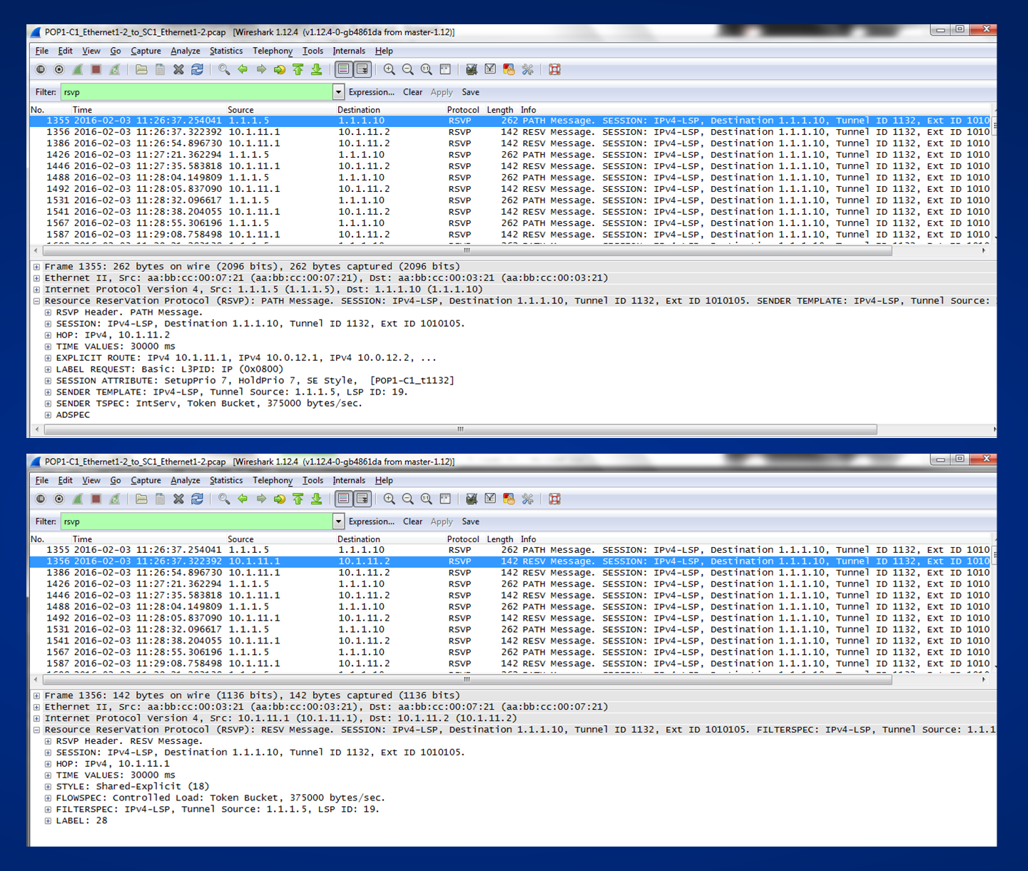
I can see many information encapsulated in both messages. I want review at least one time some of the fields, then I can glue the concepts to my mynd and have a clearer understanding about who is signalling what by mean of RSVP.
RSVP PATH MESSAGE:
I see an RSVP HEADER, this is the header format common to all RSVP Messages, all RSVP Packets have a common structure formed by a common header followed by RSVP objects.
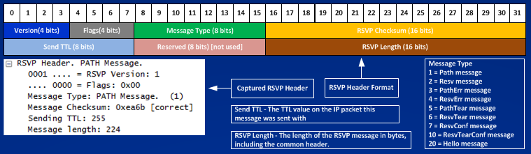
Under the header there are many RSVP objects, objects have a common structure, the first in the PATH message is a SESSION OBJECT:
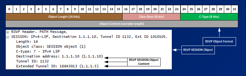
Following picture shows all other RSVP Objects found in RSVP PATH MESSAGE:
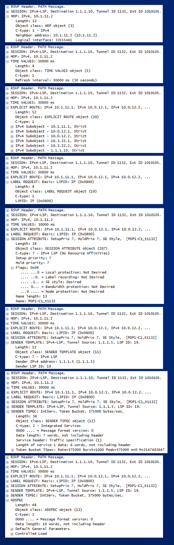
I can see that many information are encoded in an RSVP PATH MESSAGE and RESV MESSAGE, the RSVP Objects encode all the parameters needed to create and maintain an RSVP paths in the network. For example I can see in the PATH message a LABEL REQUEST Object, this object requests an mpls label to the Tunnel Tail, by deafult the Tunnel Tailend answers/generates an explicit-null (label value = 0) label because is the last router, at each hop every router sends in upstream direction (toward the Headend) label value that the upstream router should use when forwwarding traffic down the tunnel. Below you can see the RESV message generated by the Tailend Router (POP3-C2):
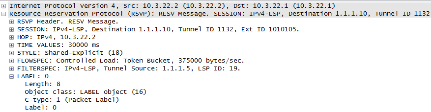
Before you lose your head trying to understand why in the captured packet we see an explicit-null (0) and using some shows command we see an implicit-null instead (label value = 3) read page (178) of “Traffic Engineering with MPLS”, here what I have in my case:
TUNNEL TAIL:
POP3-C2#show mpls traffic-eng tunnels | i Label
InLabel : Ethernet1/1, implicit-null ==> This means that POP3-C2 expect an implicit-null when traffic comes in and not an explicit-null (even if it advertised explicit-null)
OutLabel : –
NEXT UPSTREAM ROUTER:
SC2#show mpls traffic-eng tunnels | i Label
InLabel : Ethernet0/0, 28
OutLabel : Ethernet1/1, implicit-null ==> This means that SC2 interprets the explicit-null as implicit-null when sending to the tunnel-tail.
We can change what the Tunnel Tail advertises with the command “mpls traffic-eng signalling advertise implicit-null” doing this allows us to see value 3 in the captured packet, anyway in both cases with or without the command the next upstream router will see an implicit-null.
SC1#show mpls traffic-eng tunnels | i Label
InLabel : Ethernet1/2, 28
OutLabel : Ethernet0/0, 28
POP1-C1#show mpls traffic-eng tunnels | i Label
InLabel : –
OutLabel : Ethernet1/2, 28
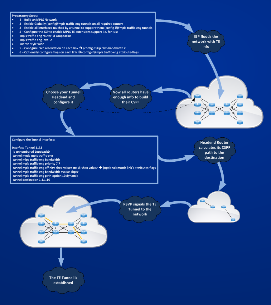
Now, I think this is not the right place for going deeper in every fields of the different RSVP objects (read the whole book as I did for this) but reading this article so far should (I hope) give an idea about how many different protocols works together to establish an MPLS TE Tunnel, let’s try to recap this with the following picture:
 Now, more or less it should be clear how an MPLS TE Tunnel is built from a Headend Router to a Tailend Router, but once the TE path is built what can I do with it?
Move to the next section ==> Forwarding Traffic Down an MPLS-TE Tunnel