In this section I want to review a simple Multicast VPN scenario.
Multicast VPN is needed inside a Provider Network when the Service Provider wants to offer Multicast Services to their MPLS/VPN customers.
The simplest option a Service Provider has is to offer the transport on its network of native multicast traffic, for example dedicating a specific multicast group for each customers and runs PIM on each of its routers. This simple solution brings some scalability problems:
1) Service Provider must enforce multicast deployment of its customers.
2) Multicast groups of different customers cannot overlap.
3) Core Routers of the Service Providers must maintain multicast information for each customers.
4) Complex and Not Scalable Multicast and Unicast Routing inside the Service Provider’s core
5) Customers have to connect to Service Provider using not VRF interfaces to use Multicast Global services offered by the SP.
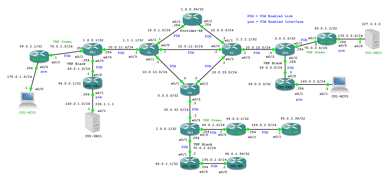
Below I set up a possible virtual Service Provider Network inside GNS3.
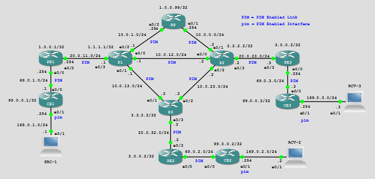 Service Provider is offering normal MPLS/IP connectivity between sites, I have not configured any vrf. P1,P2 and P3 are the P routers running OSPF as IGP, PE1, PE2 and PE3 are the Provider Edge Routers connecting the remote CEs where multicast source (SRC-1) and receivers (RCV-1 and RCV-2) are connected to receive the Multicast Service.
eBGP is the routing protocol between PE and CE and iBGP sessions are established in unicast ipv4 address familiy between each PE and the router with hostname RP that works as iBGP Route-Reflector and as Service Provider’s Rendezvousz Point.
BGP is not conifgured on P routers since we are using MPLS to switch traffic inside the core. To have multicast working I must configure PIM protocol, PIM has not its own topology exchange but it uses the unicast routing information (by default) that is present in routing tables of the routers to perform RPF check, then first thing to do is to ensure that unicat routing info is correctly distributed in the network.
Below you can see the relevant ipv4 routing information:
RP#show ip route | i B
Codes: L – local, C – connected, S – static, R – RIP, M – mobile, B – BGP
B 99.0.0.1 [200/0] via 1.0.0.1, 00:44:36
B 99.0.0.2 [200/0] via 2.0.0.2, 00:44:06
B 99.0.0.3 [200/0] via 3.0.0.3, 00:43:36
B 169.0.1.0 [200/0] via 1.0.0.1, 01:19:13
B 169.0.2.0 [200/0] via 2.0.0.2, 01:19:13
B 169.0.3.0 [200/0] via 3.0.0.3, 01:19:13
RP#ping 169.0.1.1
Type escape sequence to abort.
Sending 5, 100-byte ICMP Echos to 169.0.1.1, timeout is 2 seconds:
!!!!!
Success rate is 100 percent (5/5), round-trip min/avg/max = 5/6/11 ms
RP#ping 169.0.2.2
Type escape sequence to abort.
Sending 5, 100-byte ICMP Echos to 169.0.2.2, timeout is 2 seconds:
!!!!!
Success rate is 100 percent (5/5), round-trip min/avg/max = 2/5/7 ms
RP#ping 169.0.3.3
Type escape sequence to abort.
Sending 5, 100-byte ICMP Echos to 169.0.3.3, timeout is 2 seconds:
!!!!!
Success rate is 100 percent (5/5), round-trip min/avg/max = 5/7/10 ms
RP#traceroute 169.0.1.1
Type escape sequence to abort.
Tracing the route to 169.0.1.1
VRF info: (vrf in name/id, vrf out name/id)
1 10.0.1.1 [MPLS: Label 16 Exp 0] 1 msec 5 msec 5 msec
2 20.0.11.254 5 msec 6 msec 6 msec
3 69.0.1.1 5 msec 5 msec 5 msec
4 169.0.1.1 [AS 65001] 9 msec 8 msec 6 msec
PE1#show ip route | i B
Codes: L – local, C – connected, S – static, R – RIP, M – mobile, B – BGP
B 99.0.0.1 [20/0] via 69.0.1.1, 00:47:52
B 99.0.0.2 [200/0] via 2.0.0.2, 00:47:22
B 99.0.0.3 [200/0] via 3.0.0.3, 00:46:52
B 169.0.1.0 [20/0] via 69.0.1.1, 01:22:30
B 169.0.2.0 [200/0] via 2.0.0.2, 01:22:29
B 169.0.3.0 [200/0] via 3.0.0.3, 01:22:29
PE2#show ip route | i B
Codes: L – local, C – connected, S – static, R – RIP, M – mobile, B – BGP
B 99.0.0.1 [200/0] via 1.0.0.1, 00:48:23
B 99.0.0.2 [20/0] via 69.0.2.2, 00:47:53
B 99.0.0.3 [200/0] via 3.0.0.3, 00:47:23
B 169.0.1.0 [200/0] via 1.0.0.1, 01:23:00
B 169.0.2.0 [20/0] via 69.0.2.2, 01:23:05
B 169.0.3.0 [200/0] via 3.0.0.3, 01:23:00
PE3#show ip route | i B
Codes: L – local, C – connected, S – static, R – RIP, M – mobile, B – BGP
B 99.0.0.1 [200/0] via 1.0.0.1, 00:48:49
B 99.0.0.2 [200/0] via 2.0.0.2, 00:48:19
B 99.0.0.3 [20/0] via 69.0.3.3, 00:47:49
B 169.0.1.0 [200/0] via 1.0.0.1, 01:23:26
B 169.0.2.0 [200/0] via 2.0.0.2, 01:23:26
B 169.0.3.0 [20/0] via 69.0.3.3, 01:23:34
CE1#show ip route | i B
Codes: L – local, C – connected, S – static, R – RIP, M – mobile, B – BGP
B* 0.0.0.0/0 [20/0] via 69.0.1.254, 01:24:06
B 99.0.0.2 [20/0] via 69.0.1.254, 00:48:58
B 99.0.0.3 [20/0] via 69.0.1.254, 00:48:27
B 169.0.2.0/24 [20/0] via 69.0.1.254, 01:23:35
B 169.0.3.0/24 [20/0] via 69.0.1.254, 01:23:35
CE2#show ip route | i B
Codes: L – local, C – connected, S – static, R – RIP, M – mobile, B – BGP
B* 0.0.0.0/0 [20/0] via 69.0.2.254, 01:25:16
B 99.0.0.1 [20/0] via 69.0.2.254, 00:50:34
B 99.0.0.3 [20/0] via 69.0.2.254, 00:49:33
B 169.0.1.0/24 [20/0] via 69.0.2.254, 01:24:45
B 169.0.3.0/24 [20/0] via 69.0.2.254, 01:24:45
CE3#show ip route | i B
Codes: L – local, C – connected, S – static, R – RIP, M – mobile, B – BGP
B* 0.0.0.0/0 [20/0] via 69.0.3.254, 01:25:36
B 99.0.0.1 [20/0] via 69.0.3.254, 00:50:51
B 99.0.0.2 [20/0] via 69.0.3.254, 00:50:21
B 169.0.1.0/24 [20/0] via 69.0.3.254, 01:25:05
B 169.0.2.0/24 [20/0] via 69.0.3.254, 01:25:05
NOTE: all routing info are from Global IP Routing Table (no VRF configured)
Now, to add multicast I have to:
1) Enabling multicast-routing on all routers (Service Provider’s Routers, CE routers) ==> ip multicast-routing
2) Defining the RP and distribute RP identity all over the network. ==> Router RP is the Rendezvousz Point to its Lo0 interface, I used autorp to distribute the RP’s info.
3) Transmit some multicast traffic and have receivers on the Multicast Group
On router RP PIM configuration is:
RP#sh run int Lo0 | b int
interface Loopback0
ip address 1.0.0.99 255.255.255.255
ip pim sparse-dense-mode
RP#sh run | s ip pim send
ip pim send-rp-announce Loopback0 scope 255
ip pim send-rp-discovery Loopback0 scope 255
RP#sh run | s ip pim auto
ip pim autorp listener
RP#sh ip pim interface
Address Interface Ver/ Nbr Query DR DR
Mode Count Intvl Prior
1.0.0.99 Loopback0 v2/SD 0 30 1 1.0.0.99
10.0.0.254 Ethernet0/1 v2/SD 1 30 1 10.0.0.254
10.0.1.254 Ethernet0/2 v2/SD 1 30 1 10.0.1.254
Interfaces are configured in sparse-dense mode to use autorp feature (using autorp, groups 224.0.1.39 and 224.0.1.40 work in Dense Mode)
RP#show ip pim rp map
PIM Group-to-RP Mappings
This system is an RP (Auto-RP)
This system is an RP-mapping agent (Loopback0)
Group(s) 224.0.0.0/4
RP 1.0.0.99 (?), v2v1
Info source: 1.0.0.99 (?), elected via Auto-RP
Uptime: 04:18:30, expires: 00:02:27
RP info is distributed via PIM-AutoRP to all the routers down to the CEs where source and receivers are connected:
CE1#show ip pim rp map
PIM Group-to-RP Mappings
Group(s) 224.0.0.0/4
RP 1.0.0.99 (?), v2v1
Info source: 1.0.0.99 (?), elected via Auto-RP
Uptime: 04:22:43, expires: 00:02:43
CE1#show ip pim neighbor
PIM Neighbor Table
Mode: B – Bidir Capable, DR – Designated Router, N – Default DR Priority,
P – Proxy Capable, S – State Refresh Capable, G – GenID Capable
Neighbor Interface Uptime/Expires Ver DR
Address Prio/Mode
69.0.1.254 Ethernet0/0 04:24:56/00:01:32 v2 1 / DR S P G
To simulate a multicast source I used an IP sla probe configured to send icmp-echo packet to the multicast group 239.0.0.2:
SRC-1#show run | b sla
ip sla auto discovery
ip sla 1
icmp-echo 239.0.0.2 source-ip 169.0.1.1
threshold 1000
timeout 1000
frequency 2
ip sla schedule 1 life forever start-time now
CE2#show ip pim rp map
PIM Group-to-RP Mappings
Group(s) 224.0.0.0/4
RP 1.0.0.99 (?), v2v1
Info source: 1.0.0.99 (?), elected via Auto-RP
Uptime: 04:32:29, expires: 00:02:54
CE2#show ip pim neighbor
PIM Neighbor Table
Mode: B – Bidir Capable, DR – Designated Router, N – Default DR Priority,
P – Proxy Capable, S – State Refresh Capable, G – GenID Capable
Neighbor Interface Uptime/Expires Ver DR
Address Prio/Mode
69.0.2.254 Ethernet0/0 04:34:25/00:01:29 v2 1 / DR S P G
CE3#show ip pim rp map
PIM Group-to-RP Mappings
Group(s) 224.0.0.0/4
RP 1.0.0.99 (?), v2v1
Info source: 1.0.0.99 (?), elected via Auto-RP
Uptime: 04:33:23, expires: 00:01:59
CE3#show ip pim neighbor
PIM Neighbor Table
Mode: B – Bidir Capable, DR – Designated Router, N – Default DR Priority,
P – Proxy Capable, S – State Refresh Capable, G – GenID Capable
Neighbor Interface Uptime/Expires Ver DR
Address Prio/Mode
69.0.3.254 Ethernet0/0 04:35:10/00:01:43 v2 1 / DR S P G
Now, I have an active source sending on group 239.0.0.2, 1.0.0.99 is the RP’s IP address for all the multicast space, then also for that group. If everything is set up correctly first thing that should succed is the registration of the source on the RP.
In my service provider network I need to pay attention at how the registration message is encapsulated toward the RP. This message is generated by the Designated Router on the LAN segment of the source (CE1) and encapsulated in an unicast packet toward the RP. The registration will be complete when RP replies with an unicast packet to the DR sending a Register-Stop message for the announced source; to verify which are the involved ip addresses in this process I can check the logical Tunnel interfaces created on the routers when PIM was enabled:
CE1#sh int Tu0 | i Pim|source
Time source is hardware calendar, *14:34:04.918 UTC Wed Nov 4 2015
Description: Pim Register Tunnel (Encap) for RP 1.0.0.99
Tunnel source 69.0.1.1 (Ethernet0/0), destination 1.0.0.99
Tunnel0 source tracking subblock associated with Ethernet0/0
Set of tunnels with source Ethernet0/0, 1 member (includes iterators), on interface <OK>
CE1#show ip int br | ex una
Load for five secs: 0%/0%; one minute: 0%; five minutes: 0%
Time source is hardware calendar, *14:34:54.568 UTC Wed Nov 4 2015
Interface IP-Address OK? Method Status Protocol
Ethernet0/0 69.0.1.1 YES NVRAM up up
Ethernet0/1 169.0.1.254 YES NVRAM up up
Loopback0 99.0.0.1 YES NVRAM up up
Tunnel0 69.0.1.1 YES unset up up ==> this is created by CE1 when PIM is enabled
CE1#sh int Tu0 | i Pim|source|only
Time source is hardware calendar, *14:36:46.156 UTC Wed Nov 4 2015
Description: Pim Register Tunnel (Encap) for RP 1.0.0.99
Tunnel source 69.0.1.1 (Ethernet0/0), destination 1.0.0.99
Tunnel0 source tracking subblock associated with Ethernet0/0
Set of tunnels with source Ethernet0/0, 1 member (includes iterators), on interface <OK>
Tunnel is transmit only
CE1 use Tu0 to encapsulate the register messages from connected sources, the source address of this Tunnel is 69.0.1.1 and destination ip address is RP’s Lo0.
On RP I have TWO logical tunnels created by PIM: Tunnel0 and Tunnel1
RP#show ip int br | ex una
Interface IP-Address OK? Method Status Protocol
Ethernet0/1 10.0.0.254 YES NVRAM up up
Ethernet0/2 10.0.1.254 YES NVRAM up up
Loopback0 1.0.0.99 YES NVRAM up up
Tunnel0 1.0.0.99 YES unset up up
Tunnel1 1.0.0.99 YES unset up up
Tunnel0 is used to Encapsulated Register messages for sources that could be directly connected to the RP itself, Tunnel1 is used to decapsulate Register Messages arriving from remote Designated Routers:
RP#sh int Tu0 | i Pim|source|only
Description: Pim Register Tunnel (Encap) for RP 1.0.0.99
Tunnel source 1.0.0.99 (Loopback0), destination 1.0.0.99
Tunnel0 source tracking subblock associated with Loopback0
Set of tunnels with source Loopback0, 2 members (includes iterators), on interface <OK>
Tunnel is transmit only
RP#sh int Tu1 | i Pim|source|only
Description: Pim Register Tunnel (Decap) for RP 1.0.0.99
Tunnel source 1.0.0.99 (Loopback0), destination 1.0.0.99
Tunnel1 source tracking subblock associated with Loopback0
Set of tunnels with source Loopback0, 2 members (includes iterators), on interface <OK>
Tunnel is receive only
When RP sends its Register-Stop message to the Desingated Router, in this example, it will reply to the address 69.0.1.1 (CE1’s Tunnel0 source address), RP MUST have a valid route to that ip address, so far this is not happening because I’m not redistributing PE-CE links’ network into BGP.
RP#show ip route 69.0.1.1
% Network not in table
RP#show ip route 0.0.0.0
% Network not in table
If I look at mrib on CE1 I see:
CE1#show ip mroute 239.0.0.2
IP Multicast Routing Table
Flags: D – Dense, S – Sparse, B – Bidir Group, s – SSM Group, C – Connected,
L – Local, P – Pruned, R – RP-bit set, F – Register flag,
T – SPT-bit set, J – Join SPT, M – MSDP created entry, E – Extranet,
X – Proxy Join Timer Running, A – Candidate for MSDP Advertisement,
U – URD, I – Received Source Specific Host Report,
Z – Multicast Tunnel, z – MDT-data group sender,
Y – Joined MDT-data group, y – Sending to MDT-data group,
G – Received BGP C-Mroute, g – Sent BGP C-Mroute,
N – Received BGP Shared-Tree Prune, n – BGP C-Mroute suppressed,
Q – Received BGP S-A Route, q – Sent BGP S-A Route,
V – RD & Vector, v – Vector, p – PIM Joins on route
Outgoing interface flags: H – Hardware switched, A – Assert winner, p – PIM Join
Timers: Uptime/Expires
Interface state: Interface, Next-Hop or VCD, State/Mode
(*, 239.0.0.2), 05:03:34/stopped, RP 1.0.0.99, flags: SPF
Incoming interface: Ethernet0/0, RPF nbr 69.0.1.254
Outgoing interface list: Null
(169.0.1.1, 239.0.0.2), 05:01:36/00:02:21, flags: PFT
Incoming interface: Ethernet0/1, RPF nbr 0.0.0.0, Registering
Outgoing interface list: Null
Output shows that the source is still trying to register itself on the RP, but the Register-Stop message sent by RP never reached CE1.
Here I have more than one choice to solve this first problem:
1) I can redistribute PE-CE links into BGP
2) I can use the command “ip pim register-source Loopback0” to change the Tunnel0’s source address on CE1 used to encapsulate the Register message
I choose this second option to keep smaller routing table on PEs.
CE1(config)#ip pim register-source Loopback0
Warning: Interface is UP and is not PIM enabled.
To be used as a register tunnel source, an ip pim
mode must be configured on the interface and the interface must be up.
IOS gives me a warning ==> I used Lo0 because I have already distributed routing info about that ip address in the network, I MUST enable it for PIM.
CE1(config)#int Lo0
CE1(config-if)#ip pim sparse-mode
Now I have:
CE1#sh int Tu0 | i Pim|source|only
Description: Pim Register Tunnel (Encap) for RP 1.0.0.99
Tunnel source 99.0.0.1 (Loopback0), destination 1.0.0.99
Tunnel0 source tracking subblock associated with Loopback0
Set of tunnels with source Loopback0, 1 member (includes iterators), on interface <OK>
Tunnel is transmit only
Is this enough to register the source?
Now RP has a valid route for DR’s Ip address 99.0.0.1 and it can satisfy the RPF check against the source and it sends the Register-Stop message:
RP#show ip rpf 169.0.1.1
RPF information for ? (169.0.1.1)
RPF interface: Ethernet0/2
RPF neighbor: ? (10.0.1.1)
RPF route/mask: 169.0.1.0/24
RPF type: unicast (bgp 1)
Doing distance-preferred lookups across tables
RPF topology: ipv4 multicast base, originated from ipv4 unicast base
RP#show ip route | i 99.0.0.1
B 99.0.0.1 [200/0] via 1.0.0.1, 00:23:38
RP#
*Nov 4 16:30:59.419: PIM(0): Received v2 Register on Ethernet0/2 from 99.0.0.1
*Nov 4 16:30:59.419: for 169.0.1.1, group 239.0.0.2
*Nov 4 16:30:59.419: PIM(0): Check RP 1.0.0.99 into the (*, 239.0.0.2) entry
*Nov 4 16:30:59.419: PIM(0): Adding register decap tunnel (Tunnel1) as accepting interface of (*, 239.0.0.2).
*Nov 4 16:30:59.419: PIM(0): Adding register decap tunnel (Tunnel1) as accepting interface of (169.0.1.1, 239.0.0.2).
*Nov 4 16:30:59.419: PIM(0): Send v2 Register-Stop to 99.0.0.1 for 169.0.1.1, group 239.0.0.2
CE1(config-if)#
*Nov 4 16:30:59.417: PIM(0): Adding register encap tunnel (Tunnel0) as forwarding interface of (169.0.1.1, 239.0.0.2).
*Nov 4 16:30:59.420: PIM(0): Received v2 Register-Stop on Ethernet0/0 from 1.0.0.99
*Nov 4 16:30:59.420: PIM(0): for source 169.0.1.1, group 239.0.0.2
*Nov 4 16:30:59.420: PIM(0): Removing register encap tunnel (Tunnel0) as forwarding interface of (169.0.1.1, 239.0.0.2).
*Nov 4 16:30:59.420: PIM(0): Clear Registering flag to 1.0.0.99 for (169.0.1.1/32, 239.0.0.2) ==> you see no more “Registering” in show ip mroute 239.0.0.2
RP#show ip mroute 239.0.0.2 | b \(
(*, 239.0.0.2), 00:02:49/stopped, RP 1.0.0.99, flags: SP ==> this is the master entry created at first register packet received or at first (*,239.0.0.2)-Join received
Incoming interface: Null, RPF nbr 0.0.0.0
Outgoing interface list: Null
(169.0.1.1, 239.0.0.2), 00:02:49/00:02:10, flags: P
Incoming interface: Ethernet0/2, RPF nbr 10.0.1.1
Outgoing interface list: Null
CE1#show ip mroute 239.0.0.2 | b \(
(*, 239.0.0.2), 00:03:46/stopped, RP 1.0.0.99, flags: SPF
Incoming interface: Ethernet0/0, RPF nbr 69.0.1.254
Outgoing interface list: Null
(169.0.1.1, 239.0.0.2), 00:03:42/00:01:17, flags: PFT
Incoming interface: Ethernet0/1, RPF nbr 0.0.0.0
Outgoing interface list: Null ==> Because no receivers are present so RP has not yet sent an (S,G)-Join to toward the Source.
The core P1 router has no info yet about the group because Register and Register-Stop message are unicast tunneled between CE1 and RP.
P1#show ip mroute 239.0.0.2
Group 239.0.0.2 not found
Now it’s time to add receivers:
RCV-2(config)#int e0/1
RCV-2(config-if)#ip igmp join-group 239.0.0.2
CE2 builds (*,239.0.0.2) and sends a (*,239.0.0.2)-RP-Join up to the RP router:
CE2#show ip igmp membership 239.0.0.2 | b \*
*,239.0.0.2 169.0.2.2 00:06:13 02:27 2A Et0/1
CE2#show ip mroute 239.0.0.2 | b \(
(*, 239.0.0.2), 00:06:40/00:02:01, RP 1.0.0.99, flags: SJC
Incoming interface: Ethernet0/0, RPF nbr 69.0.2.254
Outgoing interface list:
Ethernet0/1, Forward/Sparse-Dense, 00:06:40/00:02:01
CE2 should switch from RP Tree to Source Tree as soon as it receives the first multicast packet down from RP but I see no entry is created for (169.0.1.1,239.0.0.2), this means that I have some problem, going up toward the RP router I see that (*,239.0.0.2) entries are created but no multicast packet has been switched neither on RP-Tree nor on SPT-Tree:
CE2#show ip mfib 239.0.0.2 count
Forwarding Counts: Pkt Count/Pkts per second/Avg Pkt Size/Kilobits per second
Other counts: Total/RPF failed/Other drops(OIF-null, rate-limit etc)
Default
11 routes, 8 (*,G)s, 2 (*,G/m)s
Group: 239.0.0.2
RP-tree,
SW Forwarding: 0/0/0/0, Other: 0/0/0
Groups: 1, 0.00 average sources per group
PE2#show ip mroute 239.0.0.2 | b \(
(*, 239.0.0.2), 00:14:17/00:02:56, RP 1.0.0.99, flags: S
Incoming interface: Ethernet0/3, RPF nbr 20.0.32.3
Outgoing interface list:
Ethernet0/0, Forward/Sparse-Dense, 00:14:17/00:02:56
PE2#show ip mfib 239.0.0.2 count
Forwarding Counts: Pkt Count/Pkts per second/Avg Pkt Size/Kilobits per second
Other counts: Total/RPF failed/Other drops(OIF-null, rate-limit etc)
Default
12 routes, 9 (*,G)s, 2 (*,G/m)s
Group: 239.0.0.2
RP-tree,
SW Forwarding: 0/0/0/0, Other: 0/0/0
Groups: 1, 0.00 average sources per group
P3#show ip mroute 239.0.0.2 | b \(
(*, 239.0.0.2), 00:18:24/00:02:51, RP 1.0.0.99, flags: S
Incoming interface: Ethernet0/2, RPF nbr 10.0.23.2
Outgoing interface list:
Ethernet0/3, Forward/Sparse-Dense, 00:18:24/00:02:51
——- NOTE ———–
P3 choose P2 as RPF neighbor for 1.0.0.99 because P2 has the higher IP address RPF interface compared to P1:
P3#show ip route 1.0.0.99
Routing entry for 1.0.0.99/32
Known via “ospf 1”, distance 110, metric 21, type intra area
Last update from 10.0.13.1 on Ethernet0/1, 00:47:51 ago
Routing Descriptor Blocks:
* 10.0.23.2, from 1.0.0.99, 00:47:51 ago, via Ethernet0/2
Route metric is 21, traffic share count is 1
10.0.13.1, from 1.0.0.99, 00:47:51 ago, via Ethernet0/1
Route metric is 21, traffic share count is 1
—— END NOTE ———
P2#show ip mroute 239.0.0.2 | b \(
(*, 239.0.0.2), 00:24:58/00:03:05, RP 1.0.0.99, flags: S
Incoming interface: Ethernet0/1, RPF nbr 10.0.0.254
Outgoing interface list:
Ethernet0/2, Forward/Sparse-Dense, 00:24:58/00:03:05
On RP I have both entries (*,G) and (S,G) but I have no multicast traffic forwarding:
RP#show ip mroute 239.0.0.2 | b \(
(*, 239.0.0.2), 00:51:36/00:02:47, RP 1.0.0.99, flags: S
Incoming interface: Null, RPF nbr 0.0.0.0
Outgoing interface list:
Ethernet0/1, Forward/Sparse-Dense, 00:27:16/00:02:47
(169.0.1.1, 239.0.0.2), 00:51:36/00:01:53, flags:
Incoming interface: Ethernet0/2, RPF nbr 10.0.1.1
Outgoing interface list:
Ethernet0/1, Forward/Sparse-Dense, 00:27:16/00:02:47
RP#show ip mfib 239.0.0.2 count
Forwarding Counts: Pkt Count/Pkts per second/Avg Pkt Size/Kilobits per second
Other counts: Total/RPF failed/Other drops(OIF-null, rate-limit etc)
Default
15 routes, 10 (*,G)s, 2 (*,G/m)s
Group: 239.0.0.2
RP-tree,
SW Forwarding: 0/0/0/0, Other: 0/0/0 ==> 0 Packet Forwarded on RP-tree
Source: 169.0.1.1,
SW Forwarding: 0/0/0/0, Other: 0/0/0 ==> 0 Packet Forwarded on Source-tree
Totals – Source count: 1, Packet count: 0
Groups: 1, 1.00 average sources per group
This means that neither the first multicast packet has flowed from the source to RP. Why?
Because when RP receives the (*,239.0.0.2) join from its downstream PIM neighbor toward the receiver (router P2) it sends a (169.0.1.1,239.0.0.2)-Join toward the source, but:
RP#mtrace 169.0.1.1
Type escape sequence to abort.
Mtrace from 169.0.1.1 to 10.0.1.254 via RPF
From source (?) to destination (?)
Querying full reverse path…
0 10.0.1.254
-1 10.0.1.254 ==> 10.0.1.254 PIM/MBGP [169.0.1.0/24]
-2 10.0.1.1 ==> 0.0.0.0 None No route
P1#show ip rpf 169.0.1.1
failed, no route exists
I see that when this (S,G)-Join is received by P1, P1 fails the RPF check for the source because it has no valid ip route to it (P routers are not running BGP so they have no info about customers’ routes) so I have to workaround this problem. I have a couple of choices here:
1) adding static multicast route for the source on P1, static multicast route takes precedence over unicast info for RPF check.
P1(config)#ip mroute 169.0.1.1 255.255.255.255 20.0.11.254 then RPF doesn’t fail any more:
P1#show ip rpf 169.0.1.1
RPF information for ? (169.0.1.1)
RPF interface: Ethernet0/3
RPF neighbor: ? (20.0.11.254)
RPF route/mask: 169.0.1.1/32
RPF type: multicast (static)
Doing distance-preferred lookups across tables
RPF topology: ipv4 multicast base
RP#mtrace 169.0.1.1
Type escape sequence to abort.
Mtrace from 169.0.1.1 to 10.0.1.254 via RPF
From source (?) to destination (?)
Querying full reverse path…
0 10.0.1.254
-1 10.0.1.254 ==> 10.0.1.254 PIM/MBGP [169.0.1.0/24]
-2 10.0.1.1 ==> 20.0.11.1 PIM_MT [169.0.1.1/32]
-3 20.0.11.254 ==> 69.0.1.254 PIM/MBGP [169.0.1.0/24]
-4 69.0.1.1 ==> 169.0.1.254 PIM_MT [169.0.1.0/24]
-5 169.0.1.1
Look now at the counters on RP:
RP#show ip mroute 239.0.0.2 | b \(
(*, 239.0.0.2), 01:20:16/00:02:42, RP 1.0.0.99, flags: S
Incoming interface: Null, RPF nbr 0.0.0.0
Outgoing interface list:
Ethernet0/1, Forward/Sparse-Dense, 00:55:56/00:02:42
(169.0.1.1, 239.0.0.2), 01:20:16/00:03:13, flags: T
Incoming interface: Ethernet0/2, RPF nbr 10.0.1.1
Outgoing interface list:
Ethernet0/1, Forward/Sparse-Dense, 00:55:56/00:02:42
RP#show ip mfib 239.0.0.2 count
Forwarding Counts: Pkt Count/Pkts per second/Avg Pkt Size/Kilobits per second
Other counts: Total/RPF failed/Other drops(OIF-null, rate-limit etc)
Default
15 routes, 10 (*,G)s, 2 (*,G/m)s
Group: 239.0.0.2
RP-tree,
SW Forwarding: 0/0/0/0, Other: 0/0/0
Source: 169.0.1.1,
SW Forwarding: 183/0/64/0, Other: 0/0/0
Totals – Source count: 1, Packet count: 183
Groups: 1, 1.00 average sources per group
RP#show ip mfib 239.0.0.2 count
Forwarding Counts: Pkt Count/Pkts per second/Avg Pkt Size/Kilobits per second
Other counts: Total/RPF failed/Other drops(OIF-null, rate-limit etc)
Default
15 routes, 10 (*,G)s, 2 (*,G/m)s
Group: 239.0.0.2
RP-tree,
SW Forwarding: 0/0/0/0, Other: 0/0/0
Source: 169.0.1.1,
SW Forwarding: 185/0/64/0, Other: 0/0/0
Totals – Source count: 1, Packet count: 185
Groups: 1, 1.00 average sources per group
Multicast packets from the source are flowing on the SP-Tree on RP, they enters RP from e0/2 interface and exit it from e0/1 interface to P2, on P2 I have:
P2#show ip mroute 239.0.0.2 | b \(
(*, 239.0.0.2), 00:57:29/00:03:04, RP 1.0.0.99, flags: S
Incoming interface: Ethernet0/1, RPF nbr 10.0.0.254
Outgoing interface list:
Ethernet0/2, Forward/Sparse-Dense, 00:57:29/00:03:04
On P2 again I see no (S,G) entry for the source 169.0.1.1 and multicast packet are flowing on RP-Tree and not on Source-tree:
P2#show ip mroute 239.0.0.2 count
Use “show ip mfib count” to get better response time for a large number of mroutes.
IP Multicast Statistics
5 routes using 4438 bytes of memory
3 groups, 0.66 average sources per group
Forwarding Counts: Pkt Count/Pkts per second/Avg Pkt Size/Kilobits per second
Other counts: Total/RPF failed/Other drops(OIF-null, rate-limit etc)
Group: 239.0.0.2, Source count: 0, Packets forwarded: 351, Packets received: 351
RP-tree: Forwarding: 351/0/64/0, Other: 351/0/0
A similar thing happens on P3:
P3#show ip mfib 239.0.0.2 count
Forwarding Counts: Pkt Count/Pkts per second/Avg Pkt Size/Kilobits per second
Other counts: Total/RPF failed/Other drops(OIF-null, rate-limit etc)
Default
14 routes, 10 (*,G)s, 2 (*,G/m)s
Group: 239.0.0.2
RP-tree,
SW Forwarding: 163/0/64/0, Other: 0/0/0
==> NOTE: here I have fewer packets than the packet switched on P2 (351) this means that missing packets are dropped somewhere or in the best case they are fowrarded in an unexpected way.
The problem is, again, that P2 and P3 fail RPF check toward the source because they have no valid routes to 169.0.1.1.
Here I created a spurious condition where multicast communication is on
SRC-1#ping 239.0.0.2 repeat 10
Type escape sequence to abort.
Sending 10, 100-byte ICMP Echos to 239.0.0.2, timeout is 2 seconds:
Reply to request 0 from 169.0.2.2, 3 ms
Reply to request 1 from 169.0.2.2, 2 ms
Reply to request 2 from 169.0.2.2, 1 ms
Reply to request 3 from 169.0.2.2, 2 ms
Reply to request 4 from 169.0.2.2, 1 ms
Reply to request 5 from 169.0.2.2, 1 ms
Reply to request 6 from 169.0.2.2, 1 ms
Reply to request 7 from 169.0.2.2, 1 ms
Reply to request 8 from 169.0.2.2, 2 ms
Reply to request 9 from 169.0.2.2, 2 ms
but things are not working as expected, multicast things are messed up:
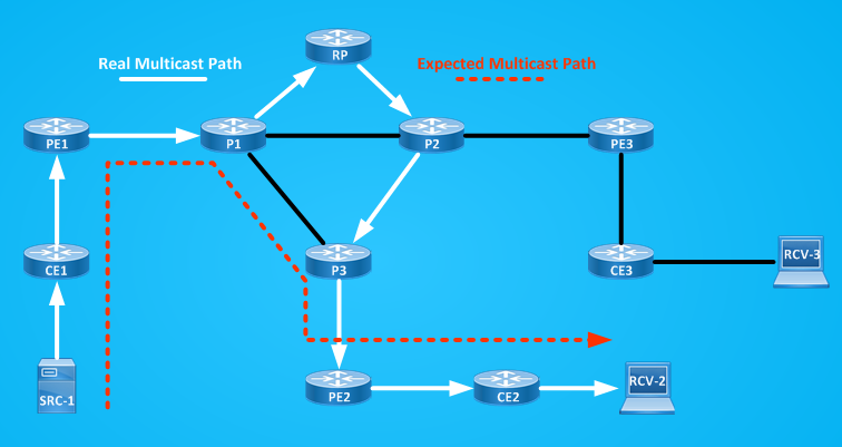
I have to solve RPF failures on ALL P routers. Here it’s simple to do this because I have only 3 P routers and a small networks, but think about a real Service Provider Network, things could be not so simple, adding multicast static routes in every P routers is not so scalable, we have also to control where new multicast active source are activated in the network to set up the right multicast static routes pointing to the right RPF neighbor.
P2(config)#ip mroute 169.0.1.1 255.255.255.255 10.0.12.1
P3(config)#ip mroute 169.0.1.1 255.255.255.255 10.0.13.1
P3#show ip mroute 239.0.0.2 | b \(
(*, 239.0.0.2), 02:09:37/00:02:44, RP 1.0.0.99, flags: S
Incoming interface: Ethernet0/2, RPF nbr 10.0.23.2
Outgoing interface list:
Ethernet0/3, Forward/Sparse-Dense, 02:09:37/00:02:44
(169.0.1.1, 239.0.0.2), 00:04:49/00:02:31, flags: T
Incoming interface: Ethernet0/1, RPF nbr 10.0.13.1, Mroute
Outgoing interface list:
Ethernet0/3, Forward/Sparse-Dense, 00:04:49/00:02:44
P1#show ip mroute 239.0.0.2 | b \(
(*, 239.0.0.2), 02:11:46/stopped, RP 1.0.0.99, flags: SP
Incoming interface: Ethernet0/2, RPF nbr 10.0.1.254
Outgoing interface list: Null
(169.0.1.1, 239.0.0.2), 01:28:06/00:03:22, flags: T
Incoming interface: Ethernet0/3, RPF nbr 20.0.11.254, Mroute
Outgoing interface list:
Ethernet0/1, Forward/Sparse-Dense, 00:04:58/00:03:24
2) Another solution I have is using BGP to exchange multicast routing info between the PEs and Ps routers.
I removed all multicast static route on P routers and I cleaned multicast group 239.0.0.2. We know so far that we need to solve the RPF check failure about the sources:
ALL PEs know about networks 169.0.x.x, for example on PE1:
PE1#show ip route 169.0.0.0
Routing entry for 169.0.0.0/24, 3 known subnets
B 169.0.1.0 [20/0] via 69.0.1.1, 00:00:03
B 169.0.2.0 [200/0] via 2.0.0.2, 02:51:29
B 169.0.3.0 [200/0] via 3.0.0.3, 02:51:29
I need to activate BGP on P routers and making neighborship between P routers and their respective PEs inside BGP ipv4 Multicast Address Family, for example on P1:
P1#show run | s r b
router bgp 1
bgp router-id 1.1.1.1
bgp log-neighbor-changes
no bgp default ipv4-unicast
neighbor 10.0.12.2 remote-as 1
neighbor 10.0.13.3 remote-as 1
neighbor 20.0.11.254 remote-as 1
!
address-family ipv4
exit-address-family
!
address-family ipv4 multicast
neighbor 10.0.12.2 activate
neighbor 10.0.13.3 activate
neighbor 20.0.11.254 activate
exit-address-family
PE1#show run | s r b
router bgp 1
bgp router-id 1.0.0.1
bgp log-neighbor-changes
no bgp default ipv4-unicast
neighbor 1.0.0.99 remote-as 1
neighbor 1.0.0.99 update-source Loopback0
neighbor 20.0.11.1 remote-as 1
neighbor 69.0.1.1 remote-as 65001
!
address-family ipv4
network 169.0.1.0 mask 255.255.255.0
neighbor 1.0.0.99 activate
neighbor 1.0.0.99 next-hop-self
neighbor 69.0.1.1 activate
neighbor 69.0.1.1 default-originate
exit-address-family
!
address-family ipv4 multicast
network 169.0.1.0 mask 255.255.255.0
neighbor 20.0.11.1 activate
neighbor 20.0.11.1 next-hop-self
exit-address-family
PE1#show bgp ipv4 multicast summary
BGP router identifier 1.0.0.1, local AS number 1
BGP table version is 1, main routing table version 1
Neighbor V AS MsgRcvd MsgSent TblVer InQ OutQ Up/Down State/PfxRcd
20.0.11.1 4 1 4 4 1 0 0 00:00:25 0
P1#show bgp ipv4 multicast summary
BGP router identifier 1.1.1.1, local AS number 1
BGP table version is 1, main routing table version 1
Neighbor V AS MsgRcvd MsgSent TblVer InQ OutQ Up/Down State/PfxRcd
10.0.12.2 4 1 0 0 1 0 0 never Idle
10.0.13.3 4 1 0 0 1 0 0 never Idle
20.0.11.254 4 1 5 5 1 0 0 00:01:28 0
So far P1 is failing RPF check as we have already seen above:
P1#show ip rpf 169.0.1.1
failed, no route exists
Then I need to add the network 169.0.1.0/24 in the “Multicast address-family advertisment” that PE1 sends to P1, since the route is already learned via BGP is not enough to add the network command under multicast address-family, so I choose to stop advertising the route from CE1 to PE1 and add a static routes on PE1 to CE1:
CE1(config)#router bgp 65001
CE1(config-router)#no network 169.0.1.0 mask 255.255.255.0
PE1(config)#router bgp 1
PE1(config-router)#address-family ipv4 unicast
PE1(config-router-af)#network 169.0.1.0 m 255.255.255.0 ==> this bring ipv4 unicast info to RP and other PEs, this is needed now because CE1 is no more advertising the route.
PE1(config-router-af)#exit
PE1(config-router)#address-family ipv4 multicast
PE1(config-router-af)#network 169.0.1.0 m 255.255.255.0 ==> this bring ipv4 multicast RPF info to P1
PE1#show bgp ipv4 multicast
BGP table version is 2, local router ID is 1.0.0.1
Status codes: s suppressed, d damped, h history, * valid, > best, i – internal,
r RIB-failure, S Stale, m multipath, b backup-path, f RT-Filter,
x best-external, a additional-path, c RIB-compressed,
Origin codes: i – IGP, e – EGP, ? – incomplete
RPKI validation codes: V valid, I invalid, N Not found
Network Next Hop Metric LocPrf Weight Path
*> 169.0.1.0/24 69.0.1.1 0 32768 i
P1#show bgp ipv4 multicast
BGP table version is 2, local router ID is 1.1.1.1
Status codes: s suppressed, d damped, h history, * valid, > best, i – internal,
r RIB-failure, S Stale, m multipath, b backup-path, f RT-Filter,
x best-external, a additional-path, c RIB-compressed,
Origin codes: i – IGP, e – EGP, ? – incomplete
RPKI validation codes: V valid, I invalid, N Not found
Network Next Hop Metric LocPrf Weight Path
*>i 169.0.1.0/24 20.0.11.254 0 100 0 i
P1#show bgp ipv4 multicast 169.0.1.0
BGP routing table entry for 169.0.1.0/24, version 2
Paths: (1 available, best #1, table 8000)
Not advertised to any peer
Refresh Epoch 1
Local
20.0.11.254 from 20.0.11.254 (1.0.0.1)
Origin IGP, metric 0, localpref 100, valid, internal, best
rx pathid: 0, tx pathid: 0x0
P1#show ip rpf 169.0.1.1
RPF information for ? (169.0.1.1)
RPF interface: Ethernet0/3
RPF neighbor: ? (20.0.11.254)
RPF route/mask: 169.0.1.0/24
RPF type: multicast (bgp 1) ==> here I see that RPF info is learned via BGP and the RPF neighbor is 20.0.11.254
Doing distance-preferred lookups across tables
RPF topology: ipv4 multicast base
Doing similar configuration on other PEs and P routers lets me have a better implementation of multicast from a scalability point of view, why?
Using BGP to transport RPF info lets me freeing P routers from having to set ip multicast static routes for every new source and think to every possible RPF neighbors for each one of this new sources.
If N is the number of new sources and M the number of P routers in my network, the number of multicast routes I should have to setup is at least N x M without considering redundacy, while using BGP I have to add the newtork of the source in the BGP Multicast address-family of the PE where the source is connected.
Someone could think that using BGP to transport multicast info on P routers force me to use BGP inside the core and this brings me back to another problem that is: I configured MPLS in the core to have P routers free from BGP and now I have to set BGP again. This is partially true, the reason you want P routers free from BGP is because you don’t want external customer routes inside your core, here BGP doesn’t inject external unicast customer’s routing info into P router’s routing table, so you still have a separation between P and PE routers from a control-plane point of view: PEs routers exchange external customer routes, P routers switch traffic via MPLS and use BGP to set up a scalable multicast backbone.
If I don’t want to be tied to set up a static route on PE for every sources behind connected CEs I can operate a PE-CE routing protocol different from BGP.
To recap this long discussion so far, a small service Provider could offer multicast services to their connected customer as described by the following picture:
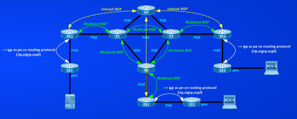
I used Named EIGRP between PEs and CEs, I redistributed EIGRP into BGP ipv4 address-family and I configured network commands for multicast address-family, below you can read whole configuration from all devices:
Pinging the multicast group from the source confirms that multicast is correctly received by joined receivers:
SRC-1#ping 239.0.0.2
Type escape sequence to abort.
Sending 1, 100-byte ICMP Echos to 239.0.0.2, timeout is 2 seconds:
Reply to request 0 from 169.0.2.2, 7 ms
Reply to request 0 from 169.0.3.3, 7 ms
CE2#show ip mroute 239.0.0.2 count
Use “show ip mfib count” to get better response time for a large number of mroutes.
IP Multicast Statistics
4 routes using 1898 bytes of memory
2 groups, 1.00 average sources per group
Forwarding Counts: Pkt Count/Pkts per second/Avg Pkt Size/Kilobits per second
Other counts: Total/RPF failed/Other drops(OIF-null, rate-limit etc)
Group: 239.0.0.2, Source count: 1, Packets forwarded: 914, Packets received: 914
RP-tree: Forwarding: 0/0/0/0, Other: 0/0/0
Source: 169.0.1.1/32, Forwarding: 914/0/64/0, Other: 914/0/0
CE3#show ip mroute 239.0.0.2 count
Use “show ip mfib count” to get better response time for a large number of mroutes.
IP Multicast Statistics
6 routes using 2712 bytes of memory
3 groups, 1.00 average sources per group
Forwarding Counts: Pkt Count/Pkts per second/Avg Pkt Size/Kilobits per second
Other counts: Total/RPF failed/Other drops(OIF-null, rate-limit etc)
Group: 239.0.0.2, Source count: 1, Packets forwarded: 913, Packets received: 913
RP-tree: Forwarding: 0/0/0/0, Other: 0/0/0
Source: 169.0.1.1/32, Forwarding: 913/0/64/0, Other: 913/0/0
Only one active source (169.0.1.1) is active on the network so far, in a more real scenario we’ll have many different customers and more than one single source. Let’s consider what we need to do in this network to deploy new sources. Suppose that RCV-2 (169.0.2.2) and RCV-3 (169.0.3.3) start to work also as sources (SRC-2 and SRC-3) of different multicast groups (239.2.2.2,239.3.3.3 respectively) and that SRC-1 will act as new receiver RCV-1 for both multicast groups and RCV-2 and RCV-3 will be receiver also for these new groups.
What I have to do to add this new multicast flows for the same customer?
1) Adding networks of the sources to the BGP multicast address-family advertisement that PEs do toward P routers.
PE2#sh run | s r b
router bgp 1
bgp router-id 2.0.0.2
bgp log-neighbor-changes
no bgp default ipv4-unicast
neighbor 1.0.0.99 remote-as 1
neighbor 1.0.0.99 update-source Loopback0
neighbor 20.0.32.3 remote-as 1
!
address-family ipv4
redistribute eigrp 65002
neighbor 1.0.0.99 activate
neighbor 1.0.0.99 next-hop-self
exit-address-family
!
address-family ipv4 multicast
network 169.0.2.0 mask 255.255.255.0 <== new source
neighbor 20.0.32.3 activate
neighbor 20.0.32.3 next-hop-self
exit-address-family
PE3#show run | s r b
router bgp 1
bgp router-id 3.0.0.3
bgp log-neighbor-changes
no bgp default ipv4-unicast
neighbor 1.0.0.99 remote-as 1
neighbor 1.0.0.99 update-source Loopback0
neighbor 20.0.23.2 remote-as 1
!
address-family ipv4
neighbor 1.0.0.99 activate
neighbor 1.0.0.99 next-hop-self
exit-address-family
!
address-family ipv4 multicast
network 169.0.3.0 mask 255.255.255.0 <== new source
neighbor 20.0.23.2 activate
neighbor 20.0.23.2 next-hop-self
exit-address-family
Activating sla probe on SRC-2 and SRC-3:
RCV-3#sh run | b sla <== this makes RCV-3 working as SRC-3
ip sla auto discovery
ip sla 3
icmp-echo 239.3.3.3 source-ip 169.0.3.3
threshold 1000
timeout 1000
frequency 5
ip sla schedule 3 life forever start-time now
RCV-2#sh run | b sla <== this makes RCV-3 working as SRC-3
ip sla auto discovery
ip sla 2
icmp-echo 239.2.2.2 source-ip 169.0.2.2
threshold 1000
timeout 1000
frequency 5
ip sla schedule 2 life forever start-time now
SRC-1#sh run int e0/1 | b interface
interface Ethernet0/1
ip address 169.0.1.1 255.255.255.0
ip igmp join-group 239.3.3.3 <== this makes SRC-1 working as RCV-1
ip igmp join-group 239.2.2.2 <== this makes SRC-1 working as RCV-1
RCV-3#sh run int e0/1 | b interface
interface Ethernet0/1
ip address 169.0.3.3 255.255.255.0
ip igmp join-group 239.2.2.2
ip igmp join-group 239.0.0.2
RCV-2#sh run int e0/1 | b interface
interface Ethernet0/1
ip address 169.0.2.2 255.255.255.0
ip igmp join-group 239.3.3.3
ip igmp join-group 239.0.0.2
SRC-1#ping 239.0.0.2
Type escape sequence to abort.
Sending 1, 100-byte ICMP Echos to 239.0.0.2, timeout is 2 seconds:
Reply to request 0 from 169.0.2.2, 1 ms
Reply to request 0 from 169.0.3.3, 1 ms
RCV-2#ping 239.2.2.2
Type escape sequence to abort.
Sending 1, 100-byte ICMP Echos to 239.2.2.2, timeout is 2 seconds:
Reply to request 0 from 169.0.3.3, 7 ms
Reply to request 0 from 169.0.1.1, 7 ms
RCV-3#ping 239.3.3.3
Type escape sequence to abort.
Sending 1, 100-byte ICMP Echos to 239.3.3.3, timeout is 2 seconds:
Reply to request 0 from 169.0.2.2, 2 ms
Reply to request 0 from 169.0.1.1, 5 ms
NOTE: Bidirectional PIM will be more efficient for multicast hosts acting as both source and receiver.
Then, my Service Provider networks is able to offer multicast services to this one single customers working with multiple sources.
The scalability issue so far can be considered as “adding networks of new sources to the BGP multicast address-family of the PE toward the directed connected P routers”
Another factor contributing to a scalability issue could be that every new customer MUST use a different multicast group from the one already used by an already connected one.
Now looks at the multicast routing table of one of the P routers:
P1#show ip mroute | b \(
(*, 239.0.0.2), 01:20:03/stopped, RP 1.0.0.99, flags: SP
Incoming interface: Ethernet0/2, RPF nbr 10.0.1.254
Outgoing interface list: Null
(169.0.1.1, 239.0.0.2), 01:20:03/00:03:07, flags: T
Incoming interface: Ethernet0/3, RPF nbr 20.0.11.254, Mbgp
Outgoing interface list:
Ethernet0/0, Forward/Sparse-Dense, 01:20:03/00:03:07
Ethernet0/1, Forward/Sparse-Dense, 01:20:03/00:03:04
(*, 239.3.3.3), 00:25:17/00:02:48, RP 1.0.0.99, flags: S
Incoming interface: Ethernet0/2, RPF nbr 10.0.1.254
Outgoing interface list:
Ethernet0/3, Forward/Sparse-Dense, 00:25:17/00:02:48
(169.0.3.3, 239.3.3.3), 00:25:15/00:02:03, flags: T
Incoming interface: Ethernet0/0, RPF nbr 10.0.12.2, Mbgp
Outgoing interface list:
Ethernet0/3, Forward/Sparse-Dense, 00:25:15/00:02:50
(*, 239.2.2.2), 00:25:10/00:02:54, RP 1.0.0.99, flags: S
Incoming interface: Ethernet0/2, RPF nbr 10.0.1.254
Outgoing interface list:
Ethernet0/3, Forward/Sparse-Dense, 00:25:10/00:02:54
(169.0.2.2, 239.2.2.2), 00:25:10/00:02:03, flags: T
Incoming interface: Ethernet0/1, RPF nbr 10.0.13.3, Mbgp
Outgoing interface list:
Ethernet0/3, Forward/Sparse-Dense, 00:25:10/00:02:57
(*, 224.0.1.39), 01:21:11/stopped, RP 0.0.0.0, flags: DC
Incoming interface: Null, RPF nbr 0.0.0.0
Outgoing interface list:
Ethernet0/1, Forward/Sparse-Dense, 01:20:42/stopped
Ethernet0/3, Forward/Sparse-Dense, 01:20:42/stopped
Ethernet0/0, Forward/Sparse-Dense, 01:20:43/stopped
Ethernet0/2, Forward/Sparse-Dense, 01:21:11/stopped
(1.0.0.99, 224.0.1.39), 01:20:11/00:02:43, flags: PT
Incoming interface: Ethernet0/2, RPF nbr 10.0.1.254
Outgoing interface list:
Ethernet0/0, Prune/Sparse-Dense, 01:20:11/00:02:29
Ethernet0/3, Prune/Sparse-Dense, 00:01:11/00:01:48
Ethernet0/1, Prune/Sparse-Dense, 01:20:11/00:02:29, A
(*, 224.0.1.40), 01:21:12/stopped, RP 0.0.0.0, flags: DCL
Incoming interface: Null, RPF nbr 0.0.0.0
Outgoing interface list:
Ethernet0/2, Forward/Sparse-Dense, 01:20:42/stopped
Ethernet0/3, Forward/Sparse-Dense, 01:20:42/stopped
Ethernet0/1, Forward/Sparse-Dense, 01:21:11/stopped
Ethernet0/0, Forward/Sparse-Dense, 01:21:12/stopped
(1.0.0.99, 224.0.1.40), 01:20:10/00:02:09, flags: LT
Incoming interface: Ethernet0/2, RPF nbr 10.0.1.254
Outgoing interface list:
Ethernet0/0, Prune/Sparse-Dense, 01:20:10/00:02:28
Ethernet0/1, Forward/Sparse-Dense, 01:20:10/stopped, A
Ethernet0/3, Forward/Sparse-Dense, 01:20:10/stopped
Without considering the Auto-RP groups, for every new sources P routers MUST add a new multicast entry to their MRIB. This is another scalability factor, more customers and more sources make Service Providers’ MRIB grow proportionally to the number of active sources.
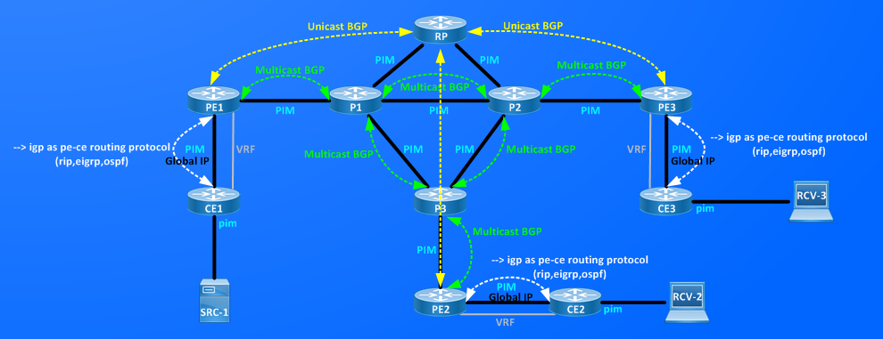
Last but not least all the multicast play I described so far, works because CEs have a link to PE in global routing table. Tipically a customer will require also an MPLS/L3 VPN service to connect its remote sites. This means that every CEs must have TWO links toward its PE, one in Global Routing Table and one in its dedicated VRF, if customer wants to operate with multicast services too. TWO links from a Service Provider (physical or logical doesn’t matter) will translate in added costs, probably you have to sell your house, your old car, and to sit on the main street to sell your old loved comics to be able to pay for this second link.
§§§§§§§ MDT §§§§§§§
MDT (Multicast Distribution Tree) can help in addressing some the of the scalablity factors I described above. First of all MDT works (not only) in vrf space then we don’t need two expensive links to SP’s PE but only one. To show how MDT works I transform my Service Provider Network in a basic SP one offering L3/MPLS-VPN to their customers, below a simple high-level view.
 We have 2 Customers CU1 and CU2 having connections in three remote sites, CU1-CE1,CU1-CE2,CU1-CE3 and CU2-CE1,CU2-CE2,CU2-CE3 each sites is services by a Service Providers’ PE routerPE1,PE2 and PE3 respectively.
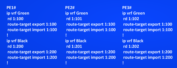
Service Provider is offering L3/MPLS-VPN service to both customers, CU1 VPN matches with VRF Black and CU2 VPN matches with vrf Green.
NOTE: This one to one relationhip between VPN and VRF is not always true, it’s valid here because VPN is simply realized exporting and importing the same Route-Target inside a VRF.
Both customers CU1 and CU2 wants to transport their multicast traffic through the Service Providers’ Network. Each customer has its own Rendezvousz Point (CU1-RP and CU2-RP), one source of multicast traffic (CU1-SRC1 and CU2-SRC3) and one receiver (CU1-RCV3, CU2-RCV1), source and receivers of the two customers are connected at diffrent sites, while RPs are both connected to CEs serviced by PE2.
Service Provider has a router (Provider-RP) working as Rendezvousz-Point and as BGP VPNV4 route-reflector.
Unicast connectivity inside the vrf is working fine, check below for a detailed view of topology with IP addresses and some connectivity tests.
 CU2-RCV1#ping 99.0.2.99 (CU2-RP)
Type escape sequence to abort.
Sending 5, 100-byte ICMP Echos to 99.0.2.99, timeout is 2 seconds:
!!!!!
Success rate is 100 percent (5/5), round-trip min/avg/max = 1/3/11 ms
CU2-RCV1#traceroute 99.0.2.99
Type escape sequence to abort.
Tracing the route to 99.0.2.99
VRF info: (vrf in name/id, vrf out name/id)
1 170.0.1.254 8 msec 5 msec 7 msec
2 70.0.1.254 5 msec 5 msec 5 msec
3 20.0.11.1 [MPLS: Labels 24/31 Exp 0] 5 msec 4 msec 5 msec
4 10.0.13.3 [MPLS: Labels 16/31 Exp 0] 7 msec 5 msec 5 msec
5 69.0.2.254 [MPLS: Label 31 Exp 0] 5 msec 7 msec 7 msec
6 69.0.2.2 7 msec 5 msec 7 msec
7 169.0.2.2 8 msec 5 msec 7 msec
CU2-RCV1#ping 170.0.3.3 (CU2-SRC3)
Type escape sequence to abort.
Sending 5, 100-byte ICMP Echos to 170.0.3.3, timeout is 2 seconds:
!!!!!
Success rate is 100 percent (5/5), round-trip min/avg/max = 1/2/4 ms
CU2-RCV1#traceroute 170.0.3.3
Type escape sequence to abort.
Tracing the route to 170.0.3.3
VRF info: (vrf in name/id, vrf out name/id)
1 170.0.1.254 0 msec 6 msec 6 msec
2 70.0.1.254 0 msec 0 msec 1 msec
3 20.0.11.1 [MPLS: Labels 23/32 Exp 0] 2 msec 0 msec 1 msec
4 10.0.12.2 [MPLS: Labels 23/32 Exp 0] 0 msec 2 msec 5 msec
5 70.0.3.254 [MPLS: Label 32 Exp 0] 4 msec 5 msec 5 msec
6 70.0.3.3 5 msec 5 msec 5 msec
7 170.0.3.3 5 msec 6 msec 6 msec
CU1-RCV3#ping 99.0.1.99 (CU1-RP)
Type escape sequence to abort.
Sending 5, 100-byte ICMP Echos to 99.0.1.99, timeout is 2 seconds:
!!!!!
Success rate is 100 percent (5/5), round-trip min/avg/max = 1/2/3 ms
CU1-RCV3#traceroute 99.0.1.99
Type escape sequence to abort.
Tracing the route to 99.0.1.99
VRF info: (vrf in name/id, vrf out name/id)
1 169.0.3.254 2 msec 7 msec 0 msec
2 69.0.3.254 1 msec 1 msec 0 msec
3 20.0.23.2 [MPLS: Labels 24/37 Exp 0] 6 msec 1 msec 1 msec
4 10.0.23.3 [MPLS: Labels 16/37 Exp 0] 1 msec 0 msec 1 msec
5 70.0.2.254 [MPLS: Label 37 Exp 0] 0 msec 2 msec 1 msec
6 70.0.2.2 0 msec 7 msec 5 msec
7 170.0.2.2 1 msec 1 msec 2 msec
CU1-RCV3#ping 169.0.1.1 (CU1-SRC1)
Type escape sequence to abort.
Sending 5, 100-byte ICMP Echos to 169.0.1.1, timeout is 2 seconds:
!!!!!
Success rate is 100 percent (5/5), round-trip min/avg/max = 5/6/10 ms
CU1-RCV3#traceroute 169.0.1.1
Type escape sequence to abort.
Tracing the route to 169.0.1.1
VRF info: (vrf in name/id, vrf out name/id)
1 169.0.3.254 5 msec 7 msec 4 msec
2 69.0.3.254 6 msec 5 msec 5 msec
3 20.0.23.2 [MPLS: Labels 18/16 Exp 0] 4 msec 6 msec 7 msec
4 10.0.12.1 [MPLS: Labels 18/16 Exp 0] 5 msec 5 msec 6 msec
5 69.0.1.254 [MPLS: Label 16 Exp 0] 5 msec 6 msec 6 msec
6 69.0.1.1 5 msec 6 msec 6 msec
7 169.0.1.1 7 msec 6 msec 7 msec
Now, before adding MDT it’s better to look at basic multicast configuration I enabled on routers.
On PEs routers links to customers are now belonging to VRFs (Green or Black) then to have PIM working on these links I MUST activate multicast routing inside the VRF:
PE1#show run | s ip multicast
ip multicast-routing
ip multicast-routing vrf Green
ip multicast-routing vrf Black
PE2#show run | s ip multicast
ip multicast-routing
ip multicast-routing vrf Green
ip multicast-routing vrf Black
PE3#show run | s ip multicast
ip multicast-routing
ip multicast-routing vrf Green
ip multicast-routing vrf Black
Then PEs have PIM neighbor in Global IP routing table and in VRFs too:
PE1#show ip pim interface
Address Interface Ver/ Nbr Query DR DR
Mode Count Intvl Prior
20.0.11.254 Ethernet0/3 v2/SD 1 30 1 20.0.11.254
PE1#show ip pim vrf Green interface
Address Interface Ver/ Nbr Query DR DR
Mode Count Intvl Prior
70.0.1.254 Ethernet0/2 v2/SD 1 30 1 70.0.1.254
PE1#show ip pim vrf Black interface
Address Interface Ver/ Nbr Query DR DR
Mode Count Intvl Prior
69.0.1.254 Ethernet0/0 v2/SD 1 30 1 69.0.1.254
PE1#show ip pim neighbor
PIM Neighbor Table
Mode: B – Bidir Capable, DR – Designated Router, N – Default DR Priority,
P – Proxy Capable, S – State Refresh Capable, G – GenID Capable
Neighbor Interface Uptime/Expires Ver DR
Address Prio/Mode
20.0.11.1 Ethernet0/3 03:36:54/00:01:21 v2 1 / S P G
PE1#show ip pim vrf Green neighbor
PIM Neighbor Table
Mode: B – Bidir Capable, DR – Designated Router, N – Default DR Priority,
P – Proxy Capable, S – State Refresh Capable, G – GenID Capable
Neighbor Interface Uptime/Expires Ver DR
Address Prio/Mode
70.0.1.1 Ethernet0/2 01:52:39/00:01:15 v2 1 / S P G
PE1#show ip pim vrf Black neighbor
PIM Neighbor Table
Mode: B – Bidir Capable, DR – Designated Router, N – Default DR Priority,
P – Proxy Capable, S – State Refresh Capable, G – GenID Capable
Neighbor Interface Uptime/Expires Ver DR
Address Prio/Mode
69.0.1.1 Ethernet0/0 03:28:20/00:01:37 v2 1 / S P G
We have three Rendezvousz-Point in play: Provider-RP, CU1-RP and CU2-RP, both in VRFs and in Global IP I’m using autorp to distribute RP identity:
Provider-RP#show ip pim rp mapping
PIM Group-to-RP Mappings
This system is an RP (Auto-RP)
This system is an RP-mapping agent (Loopback0)
Group(s) 224.0.0.0/4
RP 1.0.0.99 (?), v2v1
Info source: 1.0.0.99 (?), elected via Auto-RP
Uptime: 04:38:19, expires: 00:02:37
CU2-RP#show ip pim rp mapping
PIM Group-to-RP Mappings
This system is an RP (Auto-RP)
This system is an RP-mapping agent (Loopback0)
Group(s) 224.0.0.0/4
RP 99.0.2.99 (?), v2v1
Info source: 99.0.2.99 (?), elected via Auto-RP
Uptime: 02:28:53, expires: 00:02:02
CU1-RP#show ip pim rp mapping
PIM Group-to-RP Mappings
This system is an RP (Auto-RP)
This system is an RP-mapping agent (Loopback0)
Group(s) 224.0.0.0/4
RP 99.0.1.99 (?), v2v1
Info source: 99.0.1.99 (?), elected via Auto-RP
Uptime: 02:22:37, expires: 00:02:19
PE2 where CU-RPs are connected is the only PE that is receiving AutoRP inside the vrf so far:
PE2#show ip mroute | b \( ==> GLOBAL IP
(*, 224.0.1.40), 04:49:31/stopped, RP 0.0.0.0, flags: DCL
Incoming interface: Null, RPF nbr 0.0.0.0
Outgoing interface list:
Ethernet0/3, Forward/Sparse-Dense, 04:49:01/stopped
(1.0.0.99, 224.0.1.40), 04:48:33/00:02:28, flags: PLT
Incoming interface: Ethernet0/3, RPF nbr 20.0.32.3
Outgoing interface list: Null
PE2#show ip mroute vrf Green | b \(
(*, 224.0.1.39), 02:40:56/stopped, RP 0.0.0.0, flags: D
Incoming interface: Null, RPF nbr 0.0.0.0
Outgoing interface list:
Ethernet0/0, Forward/Sparse-Dense, 02:40:56/stopped
(99.0.2.99, 224.0.1.39), 00:02:56/00:00:03, flags: PT
Incoming interface: Ethernet0/0, RPF nbr 69.0.2.2
Outgoing interface list: Null
(*, 224.0.1.40), 04:16:08/stopped, RP 0.0.0.0, flags: DCL
Incoming interface: Null, RPF nbr 0.0.0.0
Outgoing interface list:
Ethernet0/0, Forward/Sparse-Dense, 04:16:08/stopped
(99.0.2.99, 224.0.1.40), 02:39:56/00:02:40, flags: PLTX
Incoming interface: Ethernet0/0, RPF nbr 69.0.2.2
Outgoing interface list: Null
PE2#show ip mroute vrf Black | b \(
(*, 224.0.1.39), 02:34:59/stopped, RP 0.0.0.0, flags: D
Incoming interface: Null, RPF nbr 0.0.0.0
Outgoing interface list:
Ethernet0/1, Forward/Sparse-Dense, 02:34:59/stopped
(99.0.1.99, 224.0.1.39), 00:01:59/00:01:00, flags: PT
Incoming interface: Ethernet0/1, RPF nbr 70.0.2.2
Outgoing interface list: Null
(*, 224.0.1.40), 04:15:43/stopped, RP 0.0.0.0, flags: DCL
Incoming interface: Null, RPF nbr 0.0.0.0
Outgoing interface list:
Ethernet0/1, Forward/Sparse-Dense, 04:15:43/stopped
(99.0.1.99, 224.0.1.40), 02:33:59/00:02:01, flags: PLTX
Incoming interface: Ethernet0/1, RPF nbr 70.0.2.2
Outgoing interface list: Null
PE2#show ip pim rp mapping
PIM Group-to-RP Mappings
Group(s) 224.0.0.0/4
RP 1.0.0.99 (?), v2v1
Info source: 1.0.0.99 (?), elected via Auto-RP
Uptime: 04:58:21, expires: 00:02:33
PE2#show ip pim vrf Green rp mapping
PIM Group-to-RP Mappings
Group(s) 224.0.0.0/4
RP 99.0.2.99 (?), v2v1
Info source: 99.0.2.99 (?), elected via Auto-RP
Uptime: 02:49:41, expires: 00:02:51
PE2#show ip pim vrf Black rp mapping
PIM Group-to-RP Mappings
Group(s) 224.0.0.0/4
RP 99.0.1.99 (?), v2v1
Info source: 99.0.1.99 (?), elected via Auto-RP
Uptime: 02:43:12, expires: 00:02:38
PE1#show ip mroute | b \( ==> GLOBAL IP
(*, 224.0.1.39), 05:02:38/stopped, RP 0.0.0.0, flags: D
Incoming interface: Null, RPF nbr 0.0.0.0
Outgoing interface list:
Ethernet0/3, Forward/Sparse-Dense, 05:02:38/stopped
(1.0.0.99, 224.0.1.39), 00:02:38/00:00:21, flags: PT
Incoming interface: Ethernet0/3, RPF nbr 20.0.11.1
Outgoing interface list: Null
(*, 224.0.1.40), 05:03:36/stopped, RP 0.0.0.0, flags: DCL
Incoming interface: Null, RPF nbr 0.0.0.0
Outgoing interface list:
Ethernet0/3, Forward/Sparse-Dense, 05:03:35/stopped
(1.0.0.99, 224.0.1.40), 05:02:38/00:02:17, flags: PLTX
Incoming interface: Ethernet0/3, RPF nbr 20.0.11.1
Outgoing interface list: Null
PE1#show ip mroute vrf Black | b \(
(*, 224.0.1.40), 04:55:06/00:02:01, RP 0.0.0.0, flags: DCL
Incoming interface: Null, RPF nbr 0.0.0.0
Outgoing interface list:
Ethernet0/0, Forward/Sparse-Dense, 04:55:06/stopped
PE1#show ip mroute vrf Green | b \(
(*, 224.0.1.40), 04:46:52/00:02:49, RP 0.0.0.0, flags: DCL
Incoming interface: Null, RPF nbr 0.0.0.0
Outgoing interface list:
Ethernet0/2, Forward/Sparse-Dense, 04:46:52/stopped
PE1#show ip pim rp mapping
PIM Group-to-RP Mappings
Group(s) 224.0.0.0/4
RP 1.0.0.99 (?), v2v1
Info source: 1.0.0.99 (?), elected via Auto-RP
Uptime: 04:58:05, expires: 00:02:51
PE1#show ip pim vrf Green rp mapping
PIM Group-to-RP Mappings
PE1#show ip pim vrf Black rp mapping
PIM Group-to-RP Mappings
PE3#show ip mroute | b \( ==> GLOBAL IP
(*, 224.0.1.39), 05:05:13/stopped, RP 0.0.0.0, flags: D
Incoming interface: Null, RPF nbr 0.0.0.0
Outgoing interface list:
Ethernet0/3, Forward/Sparse-Dense, 05:05:13/stopped
(1.0.0.99, 224.0.1.39), 00:02:13/00:00:46, flags: PT
Incoming interface: Ethernet0/3, RPF nbr 20.0.23.2
Outgoing interface list: Null
(*, 224.0.1.40), 05:06:11/stopped, RP 0.0.0.0, flags: DCL
Incoming interface: Null, RPF nbr 0.0.0.0
Outgoing interface list:
Ethernet0/3, Forward/Sparse-Dense, 05:06:11/stopped
(1.0.0.99, 224.0.1.40), 05:05:14/00:02:40, flags: PLTX
Incoming interface: Ethernet0/3, RPF nbr 20.0.23.2
Outgoing interface list: Null
PE3#show ip mroute vrf Green | b \(
(*, 224.0.1.40), 03:29:49/00:02:55, RP 0.0.0.0, flags: DCL
Incoming interface: Null, RPF nbr 0.0.0.0
Outgoing interface list:
Ethernet0/2, Forward/Sparse-Dense, 03:29:49/stopped
PE3#show ip mroute vrf Black | b \(
(*, 224.0.1.40), 03:29:51/00:02:24, RP 0.0.0.0, flags: DCL
Incoming interface: Null, RPF nbr 0.0.0.0
Outgoing interface list:
Ethernet0/0, Forward/Sparse-Dense, 03:29:51/stopped
PE3#show ip pim rp mapping
PIM Group-to-RP Mappings
Group(s) 224.0.0.0/4
RP 1.0.0.99 (?), v2v1
Info source: 1.0.0.99 (?), elected via Auto-RP
Uptime: 05:08:13, expires: 00:02:37
PE3#show ip pim vrf Green rp mapping
PIM Group-to-RP Mappings
PE3#show ip pim vrf Black rp mapping
PIM Group-to-RP Mappings
To connect multicast service inside a VRF I have to find a method to distribute this information to remote sites (toward other PEs). Before moving forward let’s have a look at how many Tunnels have been created by the configuration of multicast inside vrf and in global ip tables.
Multicast routing creates tunnels to encaspulate (ENCAP) Register-Message on routers that could work as Designated Router for connected sources and tunnels to decapsulate (DECAP) register messages received from Designated Routers, for example on PE2:
PE2#show ip int br | b Tunnel
Tunnel0 20.0.32.2 YES unset up up
Tunnel1 69.0.2.254 YES unset up up
Tunnel2 70.0.2.254 YES unset up up
PE2#sh int Tu0 ==> this is used by PE2 to encapsulate Register message for Provider-RP in Global IP table.
Tunnel0 is up, line protocol is up
Hardware is Tunnel
Description: Pim Register Tunnel (Encap) for RP 1.0.0.99
Interface is unnumbered. Using address of Ethernet0/3 (20.0.32.2)
MTU 17912 bytes, BW 100 Kbit/sec, DLY 50000 usec,
reliability 255/255, txload 1/255, rxload 1/255
Encapsulation TUNNEL, loopback not set
Keepalive not set
Tunnel source 20.0.32.2 (Ethernet0/3), destination 1.0.0.99
PE2#sh int Tu1 ==> this is used by PE2 to encapsulate Register message for CU2-RP in VRF Green table.
Tunnel1 is up, line protocol is up
Hardware is Tunnel
Description: Pim Register Tunnel (Encap) for RP 99.0.2.99 on VRF Green
Interface is unnumbered. Using address of Ethernet0/0 (69.0.2.254)
MTU 17912 bytes, BW 100 Kbit/sec, DLY 50000 usec,
reliability 255/255, txload 1/255, rxload 1/255
Encapsulation TUNNEL, loopback not set
Keepalive not set
Tunnel source 69.0.2.254 (Ethernet0/0), destination 99.0.2.99
PE2#sh int Tu2 ==> this is used by PE2 to encapsulate Register message for CU1-RP in VRF Black table.
Tunnel2 is up, line protocol is up
Hardware is Tunnel
Description: Pim Register Tunnel (Encap) for RP 99.0.1.99 on VRF Black
Interface is unnumbered. Using address of Ethernet0/1 (70.0.2.254)
MTU 17912 bytes, BW 100 Kbit/sec, DLY 50000 usec,
reliability 255/255, txload 1/255, rxload 1/255
Encapsulation TUNNEL, loopback not set
Keepalive not set
Tunnel source 70.0.2.254 (Ethernet0/1), destination 99.0.1.99
On routers working as RP I have both of these tunnels:
Provider-RP#show ip int br | b Tunnel
Tunnel0 1.0.0.99 YES unset up up
Tunnel1 1.0.0.99 YES unset up up
Provider-RP#sh int Tu0 ==> This is needed on RP if RP has multicast sources directly connected to it.
Tunnel0 is up, line protocol is up
Hardware is Tunnel
Description: Pim Register Tunnel (Encap) for RP 1.0.0.99
Interface is unnumbered. Using address of Loopback0 (1.0.0.99)
MTU 17912 bytes, BW 100 Kbit/sec, DLY 50000 usec,
reliability 255/255, txload 1/255, rxload 1/255
Encapsulation TUNNEL, loopback not set
Keepalive not set
Tunnel source 1.0.0.99 (Loopback0), destination 1.0.0.99
Provider-RP#sh int Tu1 ==> This Tunnel decapsulates Register Message received from Designated Routers
Tunnel1 is up, line protocol is up
Hardware is Tunnel
Description: Pim Register Tunnel (Decap) for RP 1.0.0.99
Interface is unnumbered. Using address of Loopback0 (1.0.0.99)
MTU 17920 bytes, BW 100 Kbit/sec, DLY 50000 usec,
reliability 255/255, txload 1/255, rxload 1/255
Encapsulation TUNNEL, loopback not set
Keepalive not set
Tunnel source 1.0.0.99 (Loopback0), destination 1.0.0.99
On other PEs for now I have only Tunnel0 (ENCAP) in global IP routing table:
PE1#show ip int br | b Tunnel
Tunnel0 20.0.11.254 YES unset up up
PE3#show ip int br | b Tunnel
Tunnel0 20.0.23.3 YES unset up up
Here the configs from all devices Config-Pre-MDT-vrf
Now, how does MDT works?
A Multicast Domain is a set of Multicast enabled VRFs that can sends multicast traffic to each other (reference MPLS and VPN Architecture II), in this example VRFs Green and VRFs Black configured on all 3 PEs represent TWO Multicast Domains.
The Service Provider builds a DEFAULT MULTICAST DISTRIBUTION TREE for each one of the Multicast Domain. This Default MDT is built between P routers in the backbone. MDT is a multicast tunnel through P newtork inside Service Provider Backbone.
Each Default MDT is identified by a Multicast Group (MDT-Group) allocated by the Serivce Provider , each mVRFs belongs to one MDT-Group.
The Multicast Distribution Tree will be built in the Multicast Global IP table between PEs and Ps routers. This means that when enabled MDT will set mroute entries for the defined MDT group.
In these example I will use 225.0.0.2 as MDT-Group for VRF Green and 225.0.0.1 for VRF Black.
To build a Multicast Tree for the MDT groups, P and PE routers act as ROOT and LEAVES for the group meaning that they works as SOURCE and RECEIVERS on that groups.
Provider-RP will be the router controlling the building of this tree, the information about who is the RP for the MDT groups (225.0.0.2 and 225.0.0.1) is already distributed on P and PE routers via Auto-Rp, for example:
PE1#show ip pim rp mapping 225.0.0.2
PIM Group-to-RP Mappings
Group(s) 224.0.0.0/4
RP 1.0.0.99 (?), v2v1
Info source: 1.0.0.99 (?), elected via Auto-RP
Uptime: 00:43:28, expires: 00:02:17
PE1#show ip pim rp mapping 225.0.0.1
PIM Group-to-RP Mappings
Group(s) 224.0.0.0/4
RP 1.0.0.99 (?), v2v1
Info source: 1.0.0.99 (?), elected via Auto-RP
Uptime: 00:44:23, expires: 00:02:20
PE2#show ip pim rp mapping 225.0.0.2
PIM Group-to-RP Mappings
Group(s) 224.0.0.0/4
RP 1.0.0.99 (?), v2v1
Info source: 1.0.0.99 (?), elected via Auto-RP
Uptime: 00:44:58, expires: 00:02:45
NOTE: So far I have no multicast source inside the vrf and now I close the link from CU1-RP and CU2-RP to their CEs, then I will see only multicast control plane traffic in the Service Provider Network, this will tear down Tunnel1 and Tunnel2 on PE2 and Tunnels could be recreated with different id later (tipically Tunnels are assigned id number based on what Tunnels are already present).
CU2-RP#sh run int e0/1 | b interface
interface Ethernet0/1
ip address 169.0.2.2 255.255.255.0
ip pim sparse-dense-mode
shutdown
CU1-RP#sh run int e0/0 | b interface
interface Ethernet0/0
ip address 170.0.2.2 255.255.255.0
ip pim sparse-dense-mode
shutdown
To enable MDT inside a VRF the command is:
PE1(config)#ip vrf Green
PE1(config-vrf)#mdt default 225.0.0.2
*Nov 9 20:25:08.073: %LINEPROTO-5-UPDOWN: Line protocol on Interface Tunnel1, changed state to down
Enabling MDT inside the VRF creates a new Tunnel1 on PE1:
PE1#sh ip int br | b Tunnel
Tunnel0 20.0.11.254 YES unset up up
Tunnel1 1.0.0.1 YES unset up down
PE1#sh int Tu1
Tunnel1 is up, line protocol is down
Hardware is Tunnel
Interface is unnumbered. Using address of Loopback0 (1.0.0.1)
Line protcol of the new Tunnel is down because its source ip address is inherited from Lo0 interface that is not enabled for PIM; then adding PIM to Lo0 brings up the tunnel:
PE1(config)#int Lo0
PE1(config-if)#ip pim sparse-dense-mode
PE1(config-if)#
*Nov 10 08:01:28.683: %LINEPROTO-5-UPDOWN: Line protocol on Interface Tunnel1, changed state to up
PE1#show ip int br | b Tunnel
Tunnel0 20.0.11.254 YES unset up up
Tunnel1 1.0.0.1 YES unset up up
PE1#sh int Tu1
Tunnel1 is up, line protocol is up
Hardware is Tunnel
Interface is unnumbered. Using address of Loopback0 (1.0.0.1)
MTU 17916 bytes, BW 100 Kbit/sec, DLY 50000 usec,
reliability 255/255, txload 1/255, rxload 1/255
Encapsulation TUNNEL, loopback not set
Keepalive not set
Tunnel source 1.0.0.1 (Loopback0)
When enabling MDT PE1 works as a sender for the MDT group and as a receiver for the same group 225.0.0.2. I can verifiy this behaviour looking at some show and debug ip pim messages:
PE1 Join the MDT-Group 225.0.0.2 as receiver:
PE1#show ip igmp membership 225.0.0.2 | b Interface
Channel/Group Reporter Uptime Exp. Flags Interface
*,225.0.0.2 1.0.0.1 00:26:57 stop 2VA Lo0
Since PE1 receives a “Virtual Join by itself” for the MDT group it sends a (*,G)-Join = (*,225.0.0.2) toward the Rendezvousz-Point Provider-RP (1.0.0.99)
PE1#
*Nov 10 08:01:28.688: PIM(0): Insert (*,225.0.0.2) join in nbr 20.0.11.1’s queue
*Nov 10 08:01:28.703: PIM(0): Building Join/Prune packet for nbr 20.0.11.1
*Nov 10 08:01:28.703: PIM(0): Send v2 join/prune to 20.0.11.1 (Ethernet0/3)
The (*,G)-Join arrives at P1 (20.0.11.1):
P1#
*Nov 10 08:01:28.703: PIM(0): Upstream mode for (*, 225.0.0.2) changed from 0 to 1
*Nov 10 08:01:28.703: PIM(0): Insert (*,225.0.0.2) join in nbr 10.0.1.254’s queue
*Nov 10 08:01:28.703: PIM(0): Building Join/Prune packet for nbr 10.0.1.254
*Nov 10 08:01:28.703: PIM(0): Send v2 join/prune to 10.0.1.254 (Ethernet0/2)
The (*,G)-Join arrives at Provider-RP:
Provider-RP#
*Nov 10 08:01:28.703: PIM(0): Received v2 Join/Prune on Ethernet0/2 from 10.0.1.1, to us
*Nov 10 08:01:28.703: PIM(0): Join-list: (*, 225.0.0.2), RPT-bit set, WC-bit set, S-bit set
*Nov 10 08:01:28.703: PIM(0): Check RP 1.0.0.99 into the (*, 225.0.0.2) entry
*Nov 10 08:01:28.703: PIM(0): Adding register decap tunnel (Tunnel1) as accepting interface of (*, 225.0.0.2).
*Nov 10 08:01:28.703: PIM(0): Add Ethernet0/2/10.0.1.1 to (*, 225.0.0.2), Forward state, by PIM *G Join
This first set of messages shows that PE1,P1 and Provider-RP installs a (*,225.0.0.2) entry setting in forwarding state on the RP tree the interfaces where they received the (*,225.0.0.2)-Join toward RP 1.0.0.99.
Since PE1 sets itself as a sender on the MDT group, its interface Lo0 (1.0.0.1) will work as Multicast Source on that group, then PE1 works as Designated Router and sends a PIM Register Message for the source 1.0.0.1 on the group 225.0.0.2 toward the RP:
PE1#
*Nov 10 08:01:30.303: %PIM-5-DRCHG: VRF Green: DR change from neighbor 0.0.0.0 to 1.0.0.1 on interface Tunnel1
*Nov 10 08:01:30.398: PIM(0): Check DR after interface: Loopback0 came up!
*Nov 10 08:01:30.398: PIM(0): Changing DR for Loopback0, from 0.0.0.0 to 1.0.0.1 (this system)
*Nov 10 08:01:30.398: %PIM-5-DRCHG: DR change from neighbor 0.0.0.0 to 1.0.0.1 on interface Loopback0
*Nov 10 08:01:30.398: PIM(0): Adding register encap tunnel (Tunnel0) as forwarding interface of (1.0.0.1, 225.0.0.2).
The register messages is tunneled on Tunnel0 toward the Proivder-RP where it is decapsulated on Tunnel1 interface, IOS checks if the defined RP (1.0.0.99) is mapped to the MDT-Group and then install an (S,G)=(1.0.0.1,225.0.0.2) entry, then since it has also received a (*,225.0.0.2)-Join, meaning that the are receivers interested to the group it sends an S-Join toward the source (1.0.0.1) after sending an unicast Register-Stop toward the source.
Provider-RP#
*Nov 10 08:01:31.599: PIM(0): Received v2 Register on Ethernet0/2 from 20.0.11.254
*Nov 10 08:01:31.599: for 1.0.0.1, group 225.0.0.2
*Nov 10 08:01:31.599: PIM(0): Adding register decap tunnel (Tunnel1) as accepting interface of (1.0.0.1, 225.0.0.2).
*Nov 10 08:01:31.599: PIM(0): Insert (1.0.0.1,225.0.0.2) join in nbr 10.0.1.1’s queue
*Nov 10 08:01:31.599: PIM(0): Building Join/Prune packet for nbr 10.0.1.1
*Nov 10 08:01:31.600: PIM(0): Adding v2 (1.0.0.1/32, 225.0.0.2), S-bit Join
*Nov 10 08:01:31.600: PIM(0): Send v2 join/prune to 10.0.1.1 (Ethernet0/2)
*Nov 10 08:01:31.604: PIM(0): Send v2 Register-Stop to 20.0.11.254 for 1.0.0.1, group 225.0.0.2
PE1#
*Nov 10 08:01:31.608: PIM(0): Send v2 Data-header Register to 1.0.0.99 for 1.0.0.1, group 225.0.0.2
*Nov 10 08:01:31.608: PIM(0): Received v2 Register-Stop on Ethernet0/3 from 1.0.0.99
*Nov 10 08:01:31.608: PIM(0): for source 1.0.0.1, group 225.0.0.2
*Nov 10 08:01:31.608: PIM(0): Clear Registering flag to 1.0.0.99 for (1.0.0.1/32, 225.0.0.2)
P1 forward the S-Join and sets e0/2 its e0/2 interface in forwarding on the Source-Tree:
P1#
*Nov 10 08:01:31.600: PIM(0): Received v2 Join/Prune on Ethernet0/2 from 10.0.1.254, to us
*Nov 10 08:01:31.600: PIM(0): Join-list: (1.0.0.1/32, 225.0.0.2), S-bit set
*Nov 10 08:01:31.600: PIM(0): Add Ethernet0/2/10.0.1.254 to (1.0.0.1, 225.0.0.2), Forward state, by PIM SG Join
*Nov 10 08:01:31.604: PIM(0): Insert (1.0.0.1,225.0.0.2) join in nbr 20.0.11.254’s queue
*Nov 10 08:01:31.608: PIM(0): Building Join/Prune packet for nbr 20.0.11.254
*Nov 10 08:01:31.608: PIM(0): Adding v2 (1.0.0.1/32, 225.0.0.2), S-bit Join
*Nov 10 08:01:31.608: PIM(0): Send v2 join/prune to 20.0.11.254 (Ethernet0/3)
The same does PE1:
PE1#
*Nov 10 08:01:31.608: PIM(0): Received v2 Join/Prune on Ethernet0/3 from 20.0.11.1, to us
*Nov 10 08:01:31.608: PIM(0): Join-list: (1.0.0.1/32, 225.0.0.2), S-bit set
*Nov 10 08:01:31.608: PIM(0): Add Ethernet0/3/20.0.11.1 to (1.0.0.1, 225.0.0.2), Forward state, by PIM SG Join
At the end of this process, the three routers will install both (*,255.0.0.2) and (1.0.0.1,225.0.0.2) entries in this way:
PE1#show ip mroute 225.0.0.2 | b \(
(*, 225.0.0.2), 00:14:05/stopped, RP 1.0.0.99, flags: SJCFZ
Incoming interface: Ethernet0/3, RPF nbr 20.0.11.1
Outgoing interface list:
MVRF Green, Forward/Sparse-Dense, 00:14:05/stopped ==> NOTE how in OIL we have the VRF Green.
(1.0.0.1, 225.0.0.2), 00:14:05/00:02:58, flags: PFT
Incoming interface: Loopback0, RPF nbr 0.0.0.0
Outgoing interface list: Null
P1#sh ip mroute 225.0.0.2 | b \(
(*, 225.0.0.2), 00:15:43/00:02:32, RP 1.0.0.99, flags: S
Incoming interface: Ethernet0/2, RPF nbr 10.0.1.254
Outgoing interface list:
Ethernet0/3, Forward/Sparse-Dense, 00:15:43/00:02:32
(1.0.0.1, 225.0.0.2), 00:15:43/00:02:02, flags: PR
Incoming interface: Ethernet0/2, RPF nbr 10.0.1.254
Outgoing interface list: Null
Now let’see what happens adding a second PEs to the MDT group 225.0.0.2 for vrf Green:
PE3(config)#int Lo0
PE3(config-if)#ip pim sparse-dense-mode
*Nov 10 10:26:44.723: %SYS-5-CONFIG_I: Configured from console by console
*Nov 10 10:26:45.246: %PIM-5-DRCHG: DR change from neighbor 0.0.0.0 to 3.0.0.3 on interface Loopback0
PE3(config)#ip vrf Green
PE3(config-vrf)#mdt default 225.0.0.2
PE3#
*Nov 10 10:27:12.805: %LINEPROTO-5-UPDOWN: Line protocol on Interface Tunnel1, changed state to up
*Nov 10 10:27:14.342: %PIM-5-DRCHG: VRF Green: DR change from neighbor 0.0.0.0 to 3.0.0.3 on interface Tunnel1
*Nov 10 10:27:41.155: %PIM-5-NBRCHG: VRF Green: neighbor 1.0.0.1 UP on interface Tunnel1
PE1 and PE3 becomes PIM neighbors inside VRF Green:
PE3#show ip pim vrf Green neighbor
PIM Neighbor Table
Mode: B – Bidir Capable, DR – Designated Router, N – Default DR Priority,
P – Proxy Capable, S – State Refresh Capable, G – GenID Capable
Neighbor Interface Uptime/Expires Ver DR
Address Prio/Mode
70.0.3.3 Ethernet0/2 02:50:27/00:01:42 v2 1 / S P G
1.0.0.1 Tunnel1 00:01:57/00:01:16 v2 1 / S P G
PE1#show ip pim vrf Green Neighbor
PIM Neighbor Table
Mode: B – Bidir Capable, DR – Designated Router, N – Default DR Priority,
P – Proxy Capable, S – State Refresh Capable, G – GenID Capable
Neighbor Interface Uptime/Expires Ver DR
Address Prio/Mode
70.0.1.1 Ethernet0/2 02:48:33/00:01:19 v2 1 / S P G
3.0.0.3 Tunnel1 00:00:32/00:01:41 v2 1 / DR S P G
Provider-RP adds a new entry for PE3 as source:
Provider-RP#sh ip mroute 225.0.0.2 | b \(
(*, 225.0.0.2), 00:43:33/00:03:14, RP 1.0.0.99, flags: S
Incoming interface: Null, RPF nbr 0.0.0.0
Outgoing interface list:
Ethernet0/1, Forward/Sparse-Dense, 00:03:12/00:03:14
Ethernet0/2, Forward/Sparse-Dense, 00:43:33/00:03:12
(3.0.0.3, 225.0.0.2), 00:03:12/00:01:51, flags: PT
Incoming interface: Ethernet0/1, RPF nbr 10.0.0.2
Outgoing interface list: Null
(1.0.0.1, 225.0.0.2), 00:43:33/00:02:08, flags: PT
Incoming interface: Ethernet0/2, RPF nbr 10.0.1.1
Outgoing interface list: Null
Loooking at other routers:
PE1#sh ip mroute 225.0.0.2 | b \(
(*, 225.0.0.2), 00:45:25/stopped, RP 1.0.0.99, flags: SJCFZ
Incoming interface: Ethernet0/3, RPF nbr 20.0.11.1
Outgoing interface list:
MVRF Green, Forward/Sparse-Dense, 00:45:25/stopped
(3.0.0.3, 225.0.0.2), 00:05:03/00:01:46, flags: JTZ ==> J=Join SPT, T=forwarding on SPT, Z=Multicast Tunnel ==> PE1 receives from PE3
Incoming interface: Ethernet0/3, RPF nbr 20.0.11.1
Outgoing interface list:
MVRF Green, Forward/Sparse-Dense, 00:05:03/00:00:56
(1.0.0.1, 225.0.0.2), 00:45:25/00:02:08, flags: FT ==> F=Registered Source, T=forwarding on SPT ==> PE1 is the source.
Incoming interface: Loopback0, RPF nbr 0.0.0.0
Outgoing interface list:
Ethernet0/3, Forward/Sparse-Dense, 00:05:03/00:03:19
Look now at the two (S,G) entries for 1.0.0.1 and 3.0.0.3:
PE1 has now a non NULL OIL list for itself acting as source (e0/3), the same interface (e0/3) in incoming interface for the traffic coming from PE3 and going out to its VRF Green
On PE3 I have a mirror condition:
PE3#show ip mroute 225.0.0.2 | b \(
(*, 225.0.0.2), 00:10:10/stopped, RP 1.0.0.99, flags: SJCFZ
Incoming interface: Ethernet0/3, RPF nbr 20.0.23.2
Outgoing interface list:
MVRF Green, Forward/Sparse-Dense, 00:10:10/stopped
(1.0.0.1, 225.0.0.2), 00:09:41/00:01:26, flags: JTZ
Incoming interface: Ethernet0/3, RPF nbr 20.0.23.2
Outgoing interface list:
MVRF Green, Forward/Sparse-Dense, 00:09:41/00:02:18
(3.0.0.3, 225.0.0.2), 00:10:10/00:01:48, flags: FT
Incoming interface: Loopback0, RPF nbr 0.0.0.0
Outgoing interface list:
Ethernet0/3, Forward/Sparse-Dense, 00:10:10/00:03:10
On the internal P routers P1 and P2 I have:
P1#sh ip mroute 225.0.0.2 | b \(
(*, 225.0.0.2), 00:55:45/00:02:51, RP 1.0.0.99, flags: S
Incoming interface: Ethernet0/2, RPF nbr 10.0.1.254
Outgoing interface list:
Ethernet0/3, Forward/Sparse-Dense, 00:55:45/00:02:51
(3.0.0.3, 225.0.0.2), 00:15:23/00:02:12, flags: T
Incoming interface: Ethernet0/0, RPF nbr 10.0.12.2
Outgoing interface list:
Ethernet0/3, Forward/Sparse-Dense, 00:15:23/00:02:51
(1.0.0.1, 225.0.0.2), 00:55:45/00:02:14, flags: T
Incoming interface: Ethernet0/3, RPF nbr 20.0.11.254
Outgoing interface list:
Ethernet0/0, Forward/Sparse-Dense, 00:14:54/00:03:24
P2#show ip mroute 225.0.0.2 | b \(
(*, 225.0.0.2), 00:17:10/00:03:01, RP 1.0.0.99, flags: S
Incoming interface: Ethernet0/1, RPF nbr 10.0.0.254
Outgoing interface list:
Ethernet0/3, Forward/Sparse-Dense, 00:17:10/00:03:01
(1.0.0.1, 225.0.0.2), 00:16:41/00:02:53, flags: T
Incoming interface: Ethernet0/0, RPF nbr 10.0.12.1
Outgoing interface list:
Ethernet0/3, Forward/Sparse-Dense, 00:16:41/00:03:01
(3.0.0.3, 225.0.0.2), 00:17:10/00:02:22, flags: T
Incoming interface: Ethernet0/3, RPF nbr 20.0.23.3
Outgoing interface list:
Ethernet0/0, Forward/Sparse-Dense, 00:17:10/00:03:01
Both P routers are forwarding for both PEs, they have interfaces e0/0 and e0/3 working as both transmitter and receivers based on which PE is sendig the traffic. In other words there is a Bidirectional Multicast traffic flow between PEs Tunneled inside MDT in the Service Provider Network.
Last PE to add to the game is PE2:
PE2(config)#int Lo0
PE2(config-if)#ip pim sparse-dense-mode
*Nov 10 10:49:52.259: %PIM-5-DRCHG: DR change from neighbor 0.0.0.0 to 2.0.0.2 on interface Loopback0
PE2(config)#ip vrf Green
PE2(config-vrf)#mdt default 225.0.0.2
*Nov 10 10:51:07.687: %LINEPROTO-5-UPDOWN: Line protocol on Interface Tunnel1, changed state to up
*Nov 10 10:51:09.213: %PIM-5-DRCHG: VRF Green: DR change from neighbor 0.0.0.0 to 2.0.0.2 on interface Tunnel1
After that the MRIB for the MDT-Group on the 3 PEs, Provider-RP and 3 P routers will be:

Configuring MDT I built this Default Multicast Distribution Tree for the group 225.0.0.2:
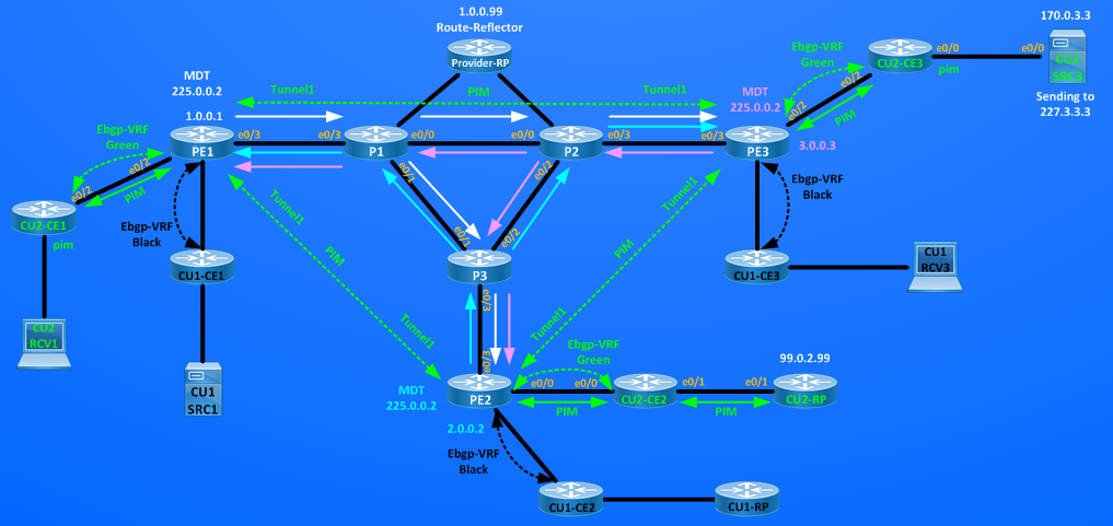
Each PEs works as Sender and Receiver for the MDT-Group and tunnels Multicast traffic from one VRF of sourcing PE to the VRF of the destination PE. The Multicast Distribution Tree is always active even if I have no Multicast Traffic that is flowing inside the VRF. From a scalability point of view, we can see that Multicast entries on P and PE routers and Proivder-RP are proportional to the number of PE where MDT is configured because each PE counts as a source.
Inside VRFs I haven’t yet multicast traffic because no source is active inside the VRF Green or Black and Routers working as Rendezvousz-Point inside each VRF have links in shutdown.
The first multicast traffic that I want enable inside VRF Green are the Auto-RP multicast messages that originate on CU2-RP and MUST reach all PEs configured to service VRF Green, in other words I want distribute the CU2-RP identity inside the VRF Green using Auto-RP tunnelled inside MDT group, bringing those messages to CEs connected to remote PEs.
CU2-RP is configured as candidate-rp and as announcing router:
CU2-RP#show ip pim rp map
PIM Group-to-RP Mappings
This system is an RP (Auto-RP)
This system is an RP-mapping agent (Loopback0)
Group(s) 224.0.0.0/4
RP 99.0.2.99 (?), v2v1
Info source: 99.0.2.99 (?), elected via Auto-RP
Uptime: 07:05:40, expires: 00:02:17
CU2-RP#show run | s ip pim
ip pim sparse-dense-mode
ip pim sparse-dense-mode
ip pim autorp listener ==> this makes Auto-RP groups (224.0.1.39 and 224.0.1.40) working in dense mode.
ip pim send-rp-announce Loopback0 scope 255 ==> CU2-RP announces itsefl as candidate-rp
ip pim send-rp-discovery Loopback0 scope 255 ==> CU2-RP distributes its identinty sending on group 224.0.1.40
Then the first multicast groups active and tunneled inside VRF Green will be 224.0.1.39 and 224.0.1.40
CU2-RP#sh ip mroute | b \(
(*, 224.0.1.39), 07:09:38/stopped, RP 0.0.0.0, flags: DCL
Incoming interface: Null, RPF nbr 0.0.0.0
Outgoing interface list:
Loopback0, Forward/Sparse-Dense, 07:09:38/stopped
(99.0.2.99, 224.0.1.39), 07:09:37/00:02:22, flags: PLT
Incoming interface: Loopback0, RPF nbr 0.0.0.0
Outgoing interface list: Null
(*, 224.0.1.40), 07:09:37/stopped, RP 0.0.0.0, flags: DCL
Incoming interface: Null, RPF nbr 0.0.0.0
Outgoing interface list:
Loopback0, Forward/Sparse-Dense, 07:09:37/stopped
(99.0.2.99, 224.0.1.40), 07:09:37/00:02:16, flags: PLT
Incoming interface: Loopback0, RPF nbr 0.0.0.0
Outgoing interface list: Null
CU2-RP#show ip igmp interface Loopback 0 | b Multicast
Multicast routing is enabled on interface
Multicast TTL threshold is 0
Multicast designated router (DR) is 99.0.2.99 (this system)
IGMP querying router is 99.0.2.99 (this system)
Multicast groups joined by this system (number of users):
224.0.1.39(1) 224.0.1.40(1)
Since e0/1 link is shutdown, inside VRF Green no info is distributed yet about who is the RP, then no multicast traffic can flow in sparse mode inside VRF Green for any source.
CU2-CE1#show ip mroute | b \(
(*, 224.0.1.40), 07:15:52/00:02:15, RP 0.0.0.0, flags: DCL
Incoming interface: Null, RPF nbr 0.0.0.0
Outgoing interface list:
Ethernet0/2, Forward/Sparse-Dense, 07:15:52/stopped
Ethernet0/0, Forward/Sparse, 07:15:52/stopped
CU2-CE1#show ip pim rp mapping
PIM Group-to-RP Mappings
PE1#show ip mroute vrf Green | b \(
(*, 224.0.1.40), 07:15:18/00:02:49, RP 0.0.0.0, flags: DCL
Incoming interface: Null, RPF nbr 0.0.0.0
Outgoing interface list:
Ethernet0/2, Forward/Sparse-Dense, 07:15:18/stopped
Tunnel1, Forward/Sparse-Dense, 04:26:48/stopped
PE1#show ip pim vrf Green rp mapping
PIM Group-to-RP Mappings
CU2-CE3#sh ip mroute | b \(
(*, 224.0.1.40), 07:19:27/00:02:43, RP 0.0.0.0, flags: DCL
Incoming interface: Null, RPF nbr 0.0.0.0
Outgoing interface list:
Ethernet0/2, Forward/Sparse-Dense, 07:19:27/stopped
Ethernet0/0, Forward/Sparse, 07:19:27/stopped
CU2-CE3#show ip pim rp mapping
PIM Group-to-RP Mappings
PE3#show ip mroute vrf Green | b \(
(*, 224.0.1.40), 07:21:00/00:02:03, RP 0.0.0.0, flags: DCL
Incoming interface: Null, RPF nbr 0.0.0.0
Outgoing interface list:
Ethernet0/2, Forward/Sparse-Dense, 07:21:00/stopped
Tunnel1, Forward/Sparse-Dense, 04:32:00/stopped
PE3#show ip pim vrf Green rp mapping
PIM Group-to-RP Mappings
CU2-CE2#show ip mroute | b \(
(*, 224.0.1.40), 07:22:42/00:02:21, RP 0.0.0.0, flags: DCL
Incoming interface: Null, RPF nbr 0.0.0.0
Outgoing interface list:
Ethernet0/0, Forward/Sparse-Dense, 07:22:42/stopped
CU2-CE2#show ip pim rp mapping
PIM Group-to-RP Mappings
PE2#show ip mroute vrf Green | b \(
(*, 224.0.1.40), 07:21:39/00:02:24, RP 0.0.0.0, flags: DCL
Incoming interface: Null, RPF nbr 0.0.0.0
Outgoing interface list:
Ethernet0/0, Forward/Sparse-Dense, 07:21:39/stopped
Tunnel1, Forward/Sparse-Dense, 04:08:44/stopped
PE2#show ip pim vrf Green rp mapping
PIM Group-to-RP Mappings
Activating link e0/1 on CU2-RP starts sending multicast info toward PE2:
CU2-RP(config)#int e0/1
CU2-RP(config-if)#no shut
*Nov 11 08:55:34.531: %PIM-5-NBRCHG: neighbor 169.0.2.254 UP on interface Ethernet0/1
*Nov 11 08:55:34.549: %PIM-5-DRCHG: DR change from neighbor 0.0.0.0 to 169.0.2.254 on interface Ethernet0/1
Bringing up the link causes some multicast event:
1) CU2-CE2
CU2-CE2#
*Nov 11 08:55:34.525: %PIM-5-NBRCHG: neighbor 169.0.2.2 UP on interface Ethernet0/1
*Nov 11 08:55:37.531: %DUAL-5-NBRCHANGE: EIGRP-IPv4 65002: Neighbor 169.0.2.2 (Ethernet0/1) is up: new adjacency
*Nov 11 08:56:00.390: %LINEPROTO-5-UPDOWN: Line protocol on Interface Tunnel0, changed state to up
CU2-CE2#show ip int br | b Tunnel
Tunnel0 169.0.2.254 YES unset up up
CU2-CE2#sh int Tu0
Tunnel0 is up, line protocol is up
Hardware is Tunnel
Description: Pim Register Tunnel (Encap) for RP 99.0.2.99
==> This is the Tunnel used to encapsulate Register toward the Rendezvousz-Point of VRF Green (99.0.2.99) and will be used in case CU2-CE2 has directly connected source.
CU2-CE2#show ip mroute | b \(
(*, 224.0.1.39), 00:16:46/stopped, RP 0.0.0.0, flags: DC
Incoming interface: Null, RPF nbr 0.0.0.0
Outgoing interface list:
Ethernet0/1, Forward/Sparse-Dense, 00:16:46/stopped
Ethernet0/0, Forward/Sparse-Dense, 00:16:46/stopped
(99.0.2.99, 224.0.1.39), 00:16:19/00:02:34, flags: T
Incoming interface: Ethernet0/1, RPF nbr 169.0.2.2
Outgoing interface list:
Ethernet0/0, Forward/Sparse-Dense, 00:16:19/stopped
(*, 224.0.1.40), 00:25:19/stopped, RP 0.0.0.0, flags: DCL
Incoming interface: Null, RPF nbr 0.0.0.0
Outgoing interface list:
Ethernet0/1, Forward/Sparse-Dense, 00:16:46/stopped
Ethernet0/0, Forward/Sparse-Dense, 00:25:19/stopped
(99.0.2.99, 224.0.1.40), 00:16:21/00:02:32, flags: LT
Incoming interface: Ethernet0/1, RPF nbr 169.0.2.2
Outgoing interface list:
Ethernet0/0, Forward/Sparse-Dense, 00:16:21/stopped
CU2-CE2#show ip pim rp mapping
PIM Group-to-RP Mappings
Group(s) 224.0.0.0/4
RP 99.0.2.99 (?), v2v1
Info source: 99.0.2.99 (?), elected via Auto-RP
Uptime: 00:17:30, expires: 00:02:22
==> CU2-CE2 now knows about who is the Rendezvousz-Point
2) PE2
PE2#
*Nov 11 08:56:00.392: %LINEPROTO-5-UPDOWN: Line protocol on Interface Tunnel2, changed state to up
PE2#show ip int br | b Tunnel
Tunnel0 20.0.32.2 YES unset up up ==> This is used to encapsulate Register Message in Global IP toward Provider-RP for directly connected sources
Tunnel1 2.0.0.2 YES unset up up ==> This is used by MDT to tunnel Multicast VRF inside MDT-Group.
Tunnel2 69.0.2.254 YES unset up up ==> This is used to encapsulate Register Message inside VRF Green toward CU2-RP (99.0.2.99)
PE2 creates a new Tunnel2:
PE2#sh int Tu2
Tunnel2 is up, line protocol is up
Hardware is Tunnel
Description: Pim Register Tunnel (Encap) for RP 99.0.2.99 on VRF Green
Interface is unnumbered. Using address of Ethernet0/0 (69.0.2.254)
MTU 17912 bytes, BW 100 Kbit/sec, DLY 50000 usec,
reliability 255/255, txload 1/255, rxload 1/255
Encapsulation TUNNEL, loopback not set
Keepalive not set
Tunnel source 69.0.2.254 (Ethernet0/0), destination 99.0.2.99
PE2#show ip pim vrf Green rp mapping
PIM Group-to-RP Mappings
Group(s) 224.0.0.0/4
RP 99.0.2.99 (?), v2v1
Info source: 99.0.2.99 (?), elected via Auto-RP
Uptime: 00:25:56, expires: 00:02:55
==> PE2 now knows about who is the Rendezvousz-Point inside VRF Green.
PE2#show ip mroute vrf Green | b \(
(*, 224.0.1.40), 00:37:51/stopped, RP 0.0.0.0, flags: DCL
Incoming interface: Null, RPF nbr 0.0.0.0
Outgoing interface list:
Ethernet0/0, Forward/Sparse-Dense, 00:37:51/stopped
Tunnel1, Forward/Sparse-Dense, 00:35:50/stopped
(99.0.2.99, 224.0.1.40), 00:28:50/00:02:52, flags: LT
Incoming interface: Ethernet0/0, RPF nbr 69.0.2.2
Outgoing interface list:
Tunnel1, Forward/Sparse-Dense, 00:28:50/stopped
Auto-RP groups inside the VRF Green are working in Dense Mode, so PE2 sets as Outgoing Interface the interface where it has PIM neighbor (except for incoming interface) inside the VRF:
PE2#show ip pim vrf Green interface
Address Interface Ver/ Nbr Query DR DR
Mode Count Intvl Prior
69.0.2.254 Ethernet0/0 v2/SD 1 30 1 69.0.2.254
2.0.0.2 Tunnel1 v2/SD 2 30 1 3.0.0.3
PE2#show ip pim vrf Green neighbor
PIM Neighbor Table
Mode: B – Bidir Capable, DR – Designated Router, N – Default DR Priority,
P – Proxy Capable, S – State Refresh Capable, G – GenID Capable
Neighbor Interface Uptime/Expires Ver DR
Address Prio/Mode
69.0.2.2 Ethernet0/0 00:39:52/00:01:15 v2 1 / S P G
1.0.0.1 Tunnel1 00:37:52/00:01:15 v2 1 / S P G
3.0.0.3 Tunnel1 00:37:54/00:01:19 v2 1 / DR S P G
Then, the Auto-RP discovery message sent by CU2-RP is tunneld inside MDT-Group 225.0.0.2 toward PE1 (1.0.0.1) and PE3 (3.0.0.3)
PE2#show ip mroute 225.0.0.2 count
Use “show ip mfib count” to get better response time for a large number of mroutes.
IP Multicast Statistics
6 routes using 3164 bytes of memory
2 groups, 2.00 average sources per group
Forwarding Counts: Pkt Count/Pkts per second/Avg Pkt Size/Kilobits per second
Other counts: Total/RPF failed/Other drops(OIF-null, rate-limit etc)
Group: 225.0.0.2, Source count: 3, Packets forwarded: 363, Packets received: 364
RP-tree: Forwarding: 0/0/0/0, Other: 0/0/0
Source: 1.0.0.1/32, Forwarding: 139/0/73/0, Other: 139/0/0
Source: 3.0.0.3/32, Forwarding: 93/0/81/0, Other: 93/0/0
Source: 2.0.0.2/32, Forwarding: 131/0/78/0, Other: 132/1/0
Looking at the above show confirms that MDT-Default-Tunnel is fowarding traffic between the 3 PEs, this traffic comprises Control Traffic for MDT (PEs builds periodic (*,G)-Join and PIM Register messages for the MDT default group) and Data Traffic (in this case the auto-rp messages of the VRF Green)
3) PE1
PE1#
*Nov 11 08:56:00.395: %LINEPROTO-5-UPDOWN: Line protocol on Interface Tunnel2, changed state to up
PE1 brings up Tunnel2 as done by PE2:
PE1#show ip int br | b Tunnel
Tunnel0 20.0.11.254 YES unset up up ==> This is used to encapsulate Register Message in Global IP toward Provider-RP for directly connected sources
Tunnel1 1.0.0.1 YES unset up up ==> This is used by MDT to tunnel Multicast VRF inside MDT-Group.
Tunnel2 70.0.1.254 YES unset up up ==> This is used to encapsulate Register Message inside VRF Green toward CU2-RP (99.0.2.99)
PE1#show ip pim vrf Green rp mapping
PIM Group-to-RP Mappings
Group(s) 224.0.0.0/4
RP 99.0.2.99 (?), v2v1
Info source: 99.0.2.99 (?), elected via Auto-RP
Uptime: 00:57:43, expires: 00:02:53
==> PE1 now knows about who is the Rendezvousz-Point inside VRF Green.
4) CU2-CE1#sh
CU2-CE1#
*Nov 11 08:56:00.403: %LINEPROTO-5-UPDOWN: Line protocol on Interface Tunnel0, changed state to up
CU2-CE1#sh int tu0
Tunnel0 is up, line protocol is up
Hardware is Tunnel
Description: Pim Register Tunnel (Encap) for RP 99.0.2.99
Interface is unnumbered. Using address of Ethernet0/2 (70.0.1.1)
MTU 17912 bytes, BW 100 Kbit/sec, DLY 50000 usec,
reliability 255/255, txload 1/255, rxload 1/255
Encapsulation TUNNEL, loopback not set
Keepalive not set
Tunnel source 70.0.1.1 (Ethernet0/2), destination 99.0.2.99
==> This is the Tunnel used to encapsulate Register toward the Rendezvousz-Point of VRF Green (99.0.2.99) and will be used in case CU2-CE1 has directly connected source (not in this example)
Similar events happens on PE3 and CU2-CE3, and RP indentity for the VRF Green is distributed over all sites inside VRF Green:
CU2-CE3#show ip pim rp mapping
PIM Group-to-RP Mappings
Group(s) 224.0.0.0/4
RP 99.0.2.99 (?), v2v1
Info source: 99.0.2.99 (?), elected via Auto-RP
Uptime: 01:05:13, expires: 00:02:17
PE3#show ip pim vrf Green rp mapping
PIM Group-to-RP Mappings
Group(s) 224.0.0.0/4
RP 99.0.2.99 (?), v2v1
Info source: 99.0.2.99 (?), elected via Auto-RP
Uptime: 01:05:33, expires: 00:02:57
Now that all the routers inside and connected to VRF Green know RP identity (99.0.2.99) I can activate a source inside the VRF Green in sparse-mode. Before doing this look at mrib table of one of the P core routers, since Auto-RP messages are tunnelled inside MDT, P routers have no info or entries about 99.0.2.99 and Auto-RP info present are the one distributed in Global IP multicast tree of the Service-Provider to distribute info about Provider-RP (1.0.0.99)
P1#show ip mroute | b \(
(*, 225.0.0.2), 01:17:20/00:02:54, RP 1.0.0.99, flags: S
Incoming interface: Ethernet0/2, RPF nbr 10.0.1.254
Outgoing interface list:
Ethernet0/3, Forward/Sparse-Dense, 01:17:16/00:02:54
(3.0.0.3, 225.0.0.2), 01:17:16/00:02:00, flags: T
Incoming interface: Ethernet0/0, RPF nbr 10.0.12.2
Outgoing interface list:
Ethernet0/3, Forward/Sparse-Dense, 01:17:16/00:02:59
(1.0.0.1, 225.0.0.2), 01:17:16/00:02:10, flags: T
Incoming interface: Ethernet0/3, RPF nbr 20.0.11.254
Outgoing interface list:
Ethernet0/1, Forward/Sparse-Dense, 01:17:16/00:02:59
Ethernet0/0, Forward/Sparse-Dense, 01:17:16/00:02:55
(2.0.0.2, 225.0.0.2), 01:17:20/00:02:27, flags: T
Incoming interface: Ethernet0/1, RPF nbr 10.0.13.3
Outgoing interface list:
Ethernet0/3, Forward/Sparse-Dense, 01:17:16/00:02:56
(*, 224.0.1.39), 01:19:17/stopped, RP 0.0.0.0, flags: DC
Incoming interface: Null, RPF nbr 0.0.0.0
Outgoing interface list:
Ethernet0/0, Forward/Sparse-Dense, 01:18:49/stopped
Ethernet0/1, Forward/Sparse-Dense, 01:18:49/stopped
Ethernet0/3, Forward/Sparse-Dense, 01:19:17/stopped
Ethernet0/2, Forward/Sparse-Dense, 01:19:17/stopped
(1.0.0.99, 224.0.1.39), 01:19:17/00:02:28, flags: PT
Incoming interface: Ethernet0/2, RPF nbr 10.0.1.254
Outgoing interface list:
Ethernet0/1, Prune/Sparse-Dense, 01:18:17/00:01:26, A
Ethernet0/0, Prune/Sparse-Dense, 01:18:17/00:01:26
Ethernet0/3, Prune/Sparse-Dense, 00:02:17/00:00:42
(*, 224.0.1.40), 01:19:18/stopped, RP 0.0.0.0, flags: DCL
Incoming interface: Null, RPF nbr 0.0.0.0
Outgoing interface list:
Ethernet0/1, Forward/Sparse-Dense, 01:19:17/stopped
Ethernet0/3, Forward/Sparse-Dense, 01:19:17/stopped
Ethernet0/2, Forward/Sparse-Dense, 01:19:17/stopped
Ethernet0/0, Forward/Sparse-Dense, 01:19:18/stopped
(1.0.0.99, 224.0.1.40), 01:19:17/00:02:04, flags: LT
Incoming interface: Ethernet0/2, RPF nbr 10.0.1.254
Outgoing interface list:
Ethernet0/1, Forward/Sparse-Dense, 01:18:19/stopped, A
Ethernet0/0, Prune/Sparse-Dense, 01:18:18/00:01:25
Ethernet0/3, Forward/Sparse-Dense, 01:19:17/stopped
The distribution of the multicast packets from a VRF inside an MDT-default group happens regardless of wheter there are receivers to remote PEs, this is good when I want to distribute control traffic inside the VRF (as I’ve done in this example sending Dense Mode Auto-RP messages), but is not good if I have some sources sending high-rate multicast flow beacuse this traffic will reach also PEs where there is not connected receivers.
For example, activating the CU2-SRC3 behind PE3 causes these multicast events in the newtork:
CU2-SRC3 will sends multicast packets on group 227.3.3.3
CU2-SRC3#sh run | b sla
ip sla auto discovery
ip sla 3
icmp-echo 227.3.3.3 source-ip 170.0.3.3 ==> source of multlicast traffic.
threshold 1000
timeout 1000
frequency 2
ip sla schedule 3 life forever start-time now
1) CU2-CE3 works as a Designated Router and sends PIM register message to the VRF Green’s Rendezvousz-Point 99.0.2.99
CU2-CE3#show run int Lo0 | b interface
interface Loopback0
ip address 99.0.2.2 255.255.255.255
ip pim sparse-mode ==> configured to use Lo0 as source of PIM register messages.
CU2-CE3#show run | s ip pim reg
ip pim register-source Loopback0 ==> this is not needed always, here I need it because PE-CE links are not redistributed in the VRFs, while Lo0 yes.
CU2-CE3#show ip pim rp mapping 227.3.3.3
PIM Group-to-RP Mappings
Group(s) 224.0.0.0/4
RP 99.0.2.99 (?), v2v1
Info source: 99.0.2.99 (?), elected via Auto-RP
Uptime: 03:38:03, expires: 00:02:10
CU2-CE3#show int Tu0
Tunnel0 is up, line protocol is up
Hardware is Tunnel
Description: Pim Register Tunnel (Encap) for RP 99.0.2.99
Interface is unnumbered. Using address of Loopback0 (99.0.2.2)
CU2-CE3#sh ip mroute 227.3.3.3 | b \(
(*, 227.3.3.3), 00:10:28/stopped, RP 99.0.2.99, flags: SPF
Incoming interface: Ethernet0/2, RPF nbr 70.0.3.254
Outgoing interface list: Null
(170.0.3.3, 227.3.3.3), 00:10:28/00:02:31, flags: PFT ==> F = the source is registered to the RP (99.0.2.99)
Incoming interface: Ethernet0/0, RPF nbr 0.0.0.0
Outgoing interface list: Null
The packet [S_IP=99.0.2.2,D_IP=99.0.2.99][PIM REGISTER, source 172.0.3.3, group 227.3.3.3] is unicast forwarded by PE3 to PE2 via MPLS/VPN and is received by CU2-RP:
2) CU2-RP
CU2-RP#show ip mroute 227.3.3.3 | b \(
(*, 227.3.3.3), 00:14:33/stopped, RP 99.0.2.99, flags: SP
Incoming interface: Null, RPF nbr 0.0.0.0
Outgoing interface list: Null
(170.0.3.3, 227.3.3.3), 00:14:33/00:02:26, flags: P
Incoming interface: Ethernet0/1, RPF nbr 169.0.2.254
Outgoing interface list: Null
NOTE: as in regular sparse-mode multicast, since no active receiver is present on VRF GReen, the only two ruters that knows about group 227.3.3.3 are the DR (CU2-CE3) and the RP (CU2-RP)
PE3#show ip mroute vrf Green 227.3.3.3
Group 227.3.3.3 not found
PE2#show ip mroute vrf Green 227.3.3.3
Group 227.3.3.3 not found
CU2-CE2#show ip mroute 227.3.3.3
Group 227.3.3.3 not found
So far I tunneled no multicast traffic, PIM register message are unicast, until now MDT worked to distribute only the Auto-RP info inside VRF Green. Next step is to activate CU2-RCV1 behind PE1:
1) CU2-RCV1
CU2-RCV1(config)#int e0/0
CU2-RCV1(config-if)#ip igmp join-group 227.3.3.3
2) CU2-CE1
First router connected to the receiver receives the membership report and adds an entry for 227.3.3.3
CU2-CE1#show ip igmp membership 227.3.3.3 | b \*
*,227.3.3.3 170.0.1.1 00:00:45 02:39 2A Et0/0
CU2-CE1#show ip mroute 227.3.3.3 | b \(
(*, 227.3.3.3), 00:02:15/stopped, RP 99.0.2.99, flags: SJC
Incoming interface: Ethernet0/2, RPF nbr 70.0.1.254
Outgoing interface list:
Ethernet0/0, Forward/Sparse, 00:02:15/00:02:06
(170.0.3.3, 227.3.3.3), 00:02:14/00:00:45, flags: JT ==> J=Joined SPT, T=Forwarding on SPT
Incoming interface: Ethernet0/2, RPF nbr 70.0.1.254
Outgoing interface list:
Ethernet0/0, Forward/Sparse, 00:02:14/00:02:06
Multicast flow is correctly received:
CU2-CE1#show ip mroute 227.3.3.3 count | b Group
Group: 227.3.3.3, Source count: 1, Packets forwarded: 143, Packets received: 143
RP-tree: Forwarding: 0/0/0/0, Other: 0/0/0
Source: 170.0.3.3/32, Forwarding: 143/0/64/0, Other: 143/0/0
CU2-CE1#show ip mroute 227.3.3.3 count | b Group
Group: 227.3.3.3, Source count: 1, Packets forwarded: 145, Packets received: 145
RP-tree: Forwarding: 0/0/0/0, Other: 0/0/0
Source: 170.0.3.3/32, Forwarding: 145/0/64/0, Other: 145/0/0
3) PE1
PE1#show ip mroute vrf Green 227.3.3.3 | b \(
(*, 227.3.3.3), 00:06:54/00:03:29, RP 99.0.2.99, flags: S
Incoming interface: Tunnel1, RPF nbr 2.0.0.2
Outgoing interface list:
Ethernet0/2, Forward/Sparse-Dense, 00:06:54/00:03:29
(170.0.3.3, 227.3.3.3), 00:06:52/00:02:33, flags: T
Incoming interface: Tunnel1, RPF nbr 3.0.0.3
Outgoing interface list:
Ethernet0/2, Forward/Sparse-Dense, 00:06:52/00:03:29
PE1 has created an entry for the group inside vrf Green, look at the incoming interface for the group, incoming interface (where the multicast flow come in from) is Tunnel1 and the RPF neighbor toward the source is PE3 (3.0.0.3), Tunnel1 is called also the Multicast Tunnel Interface (MTI).
To verify how Tunnels are in play I captured packets coming into e0/3 interface of PE1:
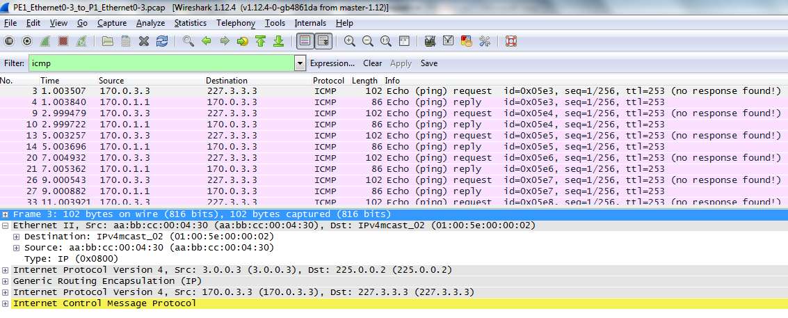 I filtered the capture on ICMP, I can see ping echo sent by the source (170.0.3.3) to the multicast group 227.3.3.3, more in detail I see an ethernet frame with:
### Source MAC = aabb.cc00.0430 (P1’s e0/3 mac address) Destination MAC = 01:00:5e:00:00:02 (multicast layer2 translation of IP 225.0.0.2)
### A first level of IP Header with Source IP = 3.0.0.3 (PE3’s Lo0), Destination IP = 225.0.0.2 (MDT Default Group for VRF Green)
### A new GRE header ==> this is followed by the original IP Multicast Packet sent by the source
### A second level of IP Header with Source IP = 170.0.3.3 Destination IP = 227.3.3.3
### The orignal ICMP Multicast packet Data sent by the source to the group 227.3.3.3
It can be clearly seen how the original Multicast IP packet is encapsulated inside the MDT Tunnel by PE3 and delivered to PE1 where it is decapsulated and forwarded as multicast ip packet (170.0.3.3,227.3.3.3) to CU2-CE1.
4) P1,P2,P3,Provider-RP
On P routers I have no evidence of the exixtence of the original multicast group:
P1#show ip mroute 227.3.3.3
Group 227.3.3.3 not found
P2#show ip mroute 227.3.3.3
Group 227.3.3.3 not found
P3#show ip mroute 227.3.3.3
Group 227.3.3.3 not found
Provider-RP#sh ip mroute 227.3.3.3
Group 227.3.3.3 not found
5) PE3
PE3#show ip mroute vrf Green 227.3.3.3 | b \(
(*, 227.3.3.3), 01:10:03/stopped, RP 99.0.2.99, flags: SP
Incoming interface: Tunnel1, RPF nbr 2.0.0.2
Outgoing interface list: Null
(170.0.3.3, 227.3.3.3), 01:10:03/00:03:13, flags: T
Incoming interface: Ethernet0/2, RPF nbr 70.0.3.3
Outgoing interface list:
Tunnel1, Forward/Sparse-Dense, 01:10:03/00:03:26 ==> this is the MTI (Multicast Tunnel Interface) interface where PE3 is sending multicast packet coming from VRF Green.
6) PE2:
PE2#show ip mroute vrf Green 227.3.3.3 | b \(
(*, 227.3.3.3), 01:14:28/00:02:53, RP 99.0.2.99, flags: S
Incoming interface: Ethernet0/0, RPF nbr 69.0.2.2
Outgoing interface list:
Tunnel1, Forward/Sparse-Dense, 01:14:28/00:02:53
(170.0.3.3, 227.3.3.3), 01:14:28/00:02:14, flags: PT
Incoming interface: Tunnel1, RPF nbr 3.0.0.3
Outgoing interface list: Null
The multicast entry is now present on PE2 too, even if we have no active receiver behind this PE, this is how MDT works when we tunnel traffic inside the MDT Default Group, the side effect of this is that traffic is disrtibuted on PE2 it is decapsulated but then is dropped because PE2 has no valid outgoing interface for that multicast flow, I can verifiy this dropping:
PE2#show ip mroute 225.0.0.2 count | i 3.0
Source: 3.0.0.3/32, Forwarding: 4075/0/86/0, Other: 4075/0/0
PE2#show ip mroute 225.0.0.2 count | i 3.0
Source: 3.0.0.3/32, Forwarding: 4077/0/86/0, Other: 4077/0/0
PE2#show ip mroute 225.0.0.2 count | i 3.0
Source: 3.0.0.3/32, Forwarding: 4078/0/86/0, Other: 4078/0/0
The above shows tell me that PE2 receives multicast flow tunneled inside MDT with PE2 as source, but where do these packets are sent?
PE2#show ip mroute vrf Green 227.3.3.3 count
Use “show ip mfib count” to get better response time for a large number of mroutes.
IP Multicast Statistics
4 routes using 2090 bytes of memory
2 groups, 1.00 average sources per group
Forwarding Counts: Pkt Count/Pkts per second/Avg Pkt Size/Kilobits per second
Other counts: Total/RPF failed/Other drops(OIF-null, rate-limit etc)
Group: 227.3.3.3, Source count: 1, Packets forwarded: 3, Packets received: 3415
RP-tree: Forwarding: 0/0/0/0, Other: 0/0/0
Source: 170.0.3.3/32, Forwarding: 3/0/64/0, Other: 3415/0/3412
PE2#show ip mroute vrf Green 227.3.3.3 count
Use “show ip mfib count” to get better response time for a large number of mroutes.
IP Multicast Statistics
4 routes using 2090 bytes of memory
2 groups, 1.00 average sources per group
Forwarding Counts: Pkt Count/Pkts per second/Avg Pkt Size/Kilobits per second
Other counts: Total/RPF failed/Other drops(OIF-null, rate-limit etc)
Group: 227.3.3.3, Source count: 1, Packets forwarded: 3, Packets received: 3416
RP-tree: Forwarding: 0/0/0/0, Other: 0/0/0
Source: 170.0.3.3/32, Forwarding: 3/0/64/0, Other: 3416/0/3413
We can see that PE2 decapsulates all the multicast packets tunneled by MDT but then it discards all these packets because outgoing interface for the original multicast group (227.3.3.3) is NULL:
PE2#show ip mroute vrf Green 227.3.3.3 | b \(
(*, 227.3.3.3), 01:56:29/00:03:09, RP 99.0.2.99, flags: S
Incoming interface: Ethernet0/0, RPF nbr 69.0.2.2
Outgoing interface list:
Tunnel1, Forward/Sparse-Dense, 01:56:29/00:03:09
(170.0.3.3, 227.3.3.3), 01:56:29/00:02:10, flags: PT
Incoming interface: Tunnel1, RPF nbr 3.0.0.3
Outgoing interface list: Null
This happens because each PEs joins the MDT-Default groups regardless of wheter receivers are present or not. To workaround this problem of unecessary flooding of traffic on the MDT Tunnel to PEs that have no connected active receivers, MDT gives us the possibility to create another MDT Tunnel called MDT-Data that has these features working together with the MDT-Default Tunnel:
1] ALL MDT CONTROL PLANE TRAFFIC IS STILL SENT OVER THE MDT DEFAULT GROUP
2] ON MDT DATA GROUP ONLY DATA TRAFFIC IS SENT – NO CONTROL TRAFFIC IS SENT OVER THIS GROUP
3] MDT DATA GROUP IT’S ACTIVATED WHEN THE AMOUNT OF DATA SENT OVER THE MDT DEFAULT GROUP GOES ABOVE A PREDEFINED THRESHOLD
4] BEFORE SENDING THE DATA INSIDE THE MDT-DATA TUNNEL THE SOURCE PE SENDS A SPECIFIC PIM MESSAGE CALLED DATA MDT-JOIN INFORMING OTHER PEs OF THE EXISTENCE OF THIS NEW GROUP, THIS SPECIAL PIM DATA MDT-JOIN IS SENT OVER THE DEFAULT MDT.
5] REMOTE PEs WILL JOIN THE NEW MDT DATA GROUP ONLY IF THEY HAVE ACTIVE RECEIVERS IN THE CORRESPONDING MULTICAST VRF.
Configuring this feature is rather simple, MDT DATA GROUP MUST BE CONFIGURED ON ALL PEs, I will use group 226.0.0.2 as MDATA-Group for VRF Green:
PE1(config)#ip vrf Green
PE1(config-vrf)#mdt ?
auto-discovery BGP auto-discovery for MVPN
data MDT data trees
default The default group
log-reuse Event logging for data MDT reuse
overlay MDT Overlay Protocol
partitioned Partitioned Multicast Distribution Tree
preference MDT preference (default pim mldp)
strict-rpf Enable strict RPF check
PE1(config-vrf)#mdt data ?
A.B.C.D IP multicast group address
list Access-list
mpls MPLS tunnel options
threshold MDT switching threshold
PE1(config-vrf)#mdt data 226.0.0.2 ?
A.B.C.D Wildcard bits
PE1(config-vrf)#mdt data 226.0.0.2 0.0.0.0 threshold ?
<1-4294967> Traffic rate in kilobits per second
PE1(config-vrf)#mdt data 226.0.0.2 0.0.0.0 threshold 1 ?
list Access-list
<cr>
PE1(config-vrf)#mdt data 226.0.0.2 0.0.0.0 threshold 1
The threshold option has been accepted, but will be deprecated in future releases
Cisco recommends using “mdt data threshold” to configure the threshold
PE1#sh run vrf Green | b ip
ip vrf Green
rd 1:100
mdt default 225.0.0.2
mdt data 226.0.0.2 0.0.0.0 threshold 1
route-target export 1:100
route-target import 1:100
==> here I match only one group with wild card 0.0.0.0, this means that ALL sources above the threshold of 1Kbit/sec will use this group 226.0.0.2, if I set a larger wildcard, for example 226.0.0.0 0.0.0.3 I will have four available groups (226.0.0.0, 226.0.0.1, 226.0.0.2, 226.0.0.3) and four different sources can use this 4 different MDT-Data Groups. The more MDT Data Groups will be active the more MDT Multicast entries will be present in Service Provider Network.
PE2#sh run | b ip vrf Green
ip vrf Green
rd 1:101
mdt default 225.0.0.2
mdt data 226.0.0.2 0.0.0.0 threshold 1
route-target export 1:100
route-target import 1:100
PE3#sh run vrf Green | b ip
ip vrf Green
rd 1:102
mdt default 225.0.0.2
mdt data 226.0.0.2 0.0.0.0 threshold 1
route-target export 1:100
route-target import 1:100
To be sure to go above the threshold I activate a new sla probe on multicast source behind PE3:
ip sla 33
icmp-echo 227.3.3.3 source-ip 170.0.3.3
request-data-size 10000 <== this causes the probe to exceed 1Kbit/sec
threshold 1000
timeout 1000
frequency 1
ip sla schedule 33 life forever start-time now
Look at the new multicast entries created on PEs and Core Routers (P and Provider-RP):
PE3#show ip mroute 226.0.0.2
IP Multicast Routing Table
Flags: D – Dense, S – Sparse, B – Bidir Group, s – SSM Group, C – Connected,
L – Local, P – Pruned, R – RP-bit set, F – Register flag,
T – SPT-bit set, J – Join SPT, M – MSDP created entry, E – Extranet,
X – Proxy Join Timer Running, A – Candidate for MSDP Advertisement,
U – URD, I – Received Source Specific Host Report,
Z – Multicast Tunnel, z – MDT-data group sender,
Y – Joined MDT-data group, y – Sending to MDT-data group,
G – Received BGP C-Mroute, g – Sent BGP C-Mroute,
N – Received BGP Shared-Tree Prune, n – BGP C-Mroute suppressed,
Q – Received BGP S-A Route, q – Sent BGP S-A Route,
V – RD & Vector, v – Vector, p – PIM Joins on route
Outgoing interface flags: H – Hardware switched, A – Assert winner, p – PIM Join
Timers: Uptime/Expires
Interface state: Interface, Next-Hop or VCD, State/Mode
(*, 226.0.0.2), 00:03:51/stopped, RP 1.0.0.99, flags: SPFz
Incoming interface: Ethernet0/3, RPF nbr 20.0.23.2
Outgoing interface list: Null
(3.0.0.3, 226.0.0.2), 00:03:48/00:01:42, flags: FTz ==> F=3.0.0.3 is registered to Provider-RP, T=we switched on SPT, z = z – MDT-data group sender
Incoming interface: Loopback0, RPF nbr 0.0.0.0
Outgoing interface list:
Ethernet0/3, Forward/Sparse-Dense, 00:03:48/00:02:37
P2#show ip mroute 226.0.0.2 | b \(
(*, 226.0.0.2), 00:06:15/stopped, RP 1.0.0.99, flags: SP
Incoming interface: Ethernet0/1, RPF nbr 10.0.0.254
Outgoing interface list: Null
(3.0.0.3, 226.0.0.2), 00:06:15/00:03:10, flags: T
Incoming interface: Ethernet0/3, RPF nbr 20.0.23.3
Outgoing interface list:
Ethernet0/0, Forward/Sparse-Dense, 00:06:15/00:03:09
Provider-RP#show ip mroute 226.0.0.2 | b \(
(*, 226.0.0.2), 00:05:40/00:02:46, RP 1.0.0.99, flags: S
Incoming interface: Null, RPF nbr 0.0.0.0
Outgoing interface list:
Ethernet0/2, Forward/Sparse-Dense, 00:05:40/00:02:46
(3.0.0.3, 226.0.0.2), 00:05:37/00:01:24, flags: PT
Incoming interface: Ethernet0/1, RPF nbr 10.0.0.2
Outgoing interface list: Null
P1#show ip mroute 226.0.0.2 | b \(
(*, 226.0.0.2), 00:06:40/00:02:43, RP 1.0.0.99, flags: S
Incoming interface: Ethernet0/2, RPF nbr 10.0.1.254
Outgoing interface list:
Ethernet0/3, Forward/Sparse-Dense, 00:06:40/00:02:43
(3.0.0.3, 226.0.0.2), 00:06:37/00:02:44, flags: T
Incoming interface: Ethernet0/0, RPF nbr 10.0.12.2
Outgoing interface list:
Ethernet0/3, Forward/Sparse-Dense, 00:06:37/00:02:43
PE1#show ip mroute 226.0.0.2 | b \(
(*, 226.0.0.2), 00:08:14/stopped, RP 1.0.0.99, flags: SJCZ
Incoming interface: Ethernet0/3, RPF nbr 20.0.11.1
Outgoing interface list:
MVRF Green, Forward/Sparse-Dense, 00:08:14/stopped
(3.0.0.3, 226.0.0.2), 00:08:11/00:02:38, flags: JTZ
Incoming interface: Ethernet0/3, RPF nbr 20.0.11.1
Outgoing interface list:
MVRF Green, Forward/Sparse-Dense, 00:08:11/00:00:48
P3#show ip mroute 226.0.0.2
Group 226.0.0.2 not found
PE2#show ip mroute 226.0.0.2
Group 226.0.0.2 not found
I can see that the multicast entry is created on PE3,P2,P1,PE1 but is not created on P3 and PE2. This happens becasue PE2 has not an active receiver so it “discards” the MDT-Data-Join coming from PE3. This helps in not forwarding unecessary multicast traffic to PE2:
If I look at counters of the MDATA Groups on PEs now I see that on the MDT Default-Group 225.0.0.2 only few packets are forwarded and are the control packets (PEs builds periodic (*,G)-Join and PIM Register messages for the MDT default group) the data packets coming from the source are forwarded over the MDT-DATA-GROUP, for example on PE1:
PE1#show ip mroute 225.0.0.2 count
Load for five secs: 0%/0%; one minute: 0%; five minutes: 0%
Time source is hardware calendar, *16:08:28.752 UTC Wed Nov 11 2015
Use “show ip mfib count” to get better response time for a large number of mroutes.
IP Multicast Statistics
10 routes using 4962 bytes of memory
4 groups, 1.50 average sources per group
Forwarding Counts: Pkt Count/Pkts per second/Avg Pkt Size/Kilobits per second
Other counts: Total/RPF failed/Other drops(OIF-null, rate-limit etc)
Group: 225.0.0.2, Source count: 3, Packets forwarded: 9408, Packets received: 9409
RP-tree: Forwarding: 0/0/0/0, Other: 0/0/0
Source: 2.0.0.2/32, Forwarding: 1466/0/77/0, Other: 1466/0/0
Source: 3.0.0.3/32, Forwarding: 6205/0/93/0, Other: 6205/0/0
Source: 1.0.0.1/32, Forwarding: 1737/0/75/0, Other: 1738/1/0
PE1#show ip mroute 225.0.0.2 count
Load for five secs: 0%/0%; one minute: 0%; five minutes: 0%
Time source is hardware calendar, *16:08:34.405 UTC Wed Nov 11 2015
Use “show ip mfib count” to get better response time for a large number of mroutes.
IP Multicast Statistics
10 routes using 4962 bytes of memory
4 groups, 1.50 average sources per group
Forwarding Counts: Pkt Count/Pkts per second/Avg Pkt Size/Kilobits per second
Other counts: Total/RPF failed/Other drops(OIF-null, rate-limit etc)
Group: 225.0.0.2, Source count: 3, Packets forwarded: 9411, Packets received: 9412
RP-tree: Forwarding: 0/0/0/0, Other: 0/0/0
Source: 2.0.0.2/32, Forwarding: 1466/0/77/0, Other: 1466/0/0
Source: 3.0.0.3/32, Forwarding: 6206/0/93/0, Other: 6206/0/0
Source: 1.0.0.1/32, Forwarding: 1739/0/75/0, Other: 1740/1/0
PE1#show ip mroute 226.0.0.2 count
Load for five secs: 0%/0%; one minute: 0%; five minutes: 0%
Time source is hardware calendar, *16:09:12.041 UTC Wed Nov 11 2015
Use “show ip mfib count” to get better response time for a large number of mroutes.
IP Multicast Statistics
10 routes using 4962 bytes of memory
4 groups, 1.50 average sources per group
Forwarding Counts: Pkt Count/Pkts per second/Avg Pkt Size/Kilobits per second
Other counts: Total/RPF failed/Other drops(OIF-null, rate-limit etc)
Group: 226.0.0.2, Source count: 1, Packets forwarded: 11989, Packets received: 11989
RP-tree: Forwarding: 0/0/0/0, Other: 0/0/0
Source: 3.0.0.3/32, Forwarding: 11989/13/730/81, Other: 11989/0/0
PE1#show ip mroute 226.0.0.2 count
Load for five secs: 0%/0%; one minute: 0%; five minutes: 0%
Time source is hardware calendar, *16:09:18.357 UTC Wed Nov 11 2015
Use “show ip mfib count” to get better response time for a large number of mroutes.
IP Multicast Statistics
10 routes using 4962 bytes of memory
4 groups, 1.50 average sources per group
Forwarding Counts: Pkt Count/Pkts per second/Avg Pkt Size/Kilobits per second
Other counts: Total/RPF failed/Other drops(OIF-null, rate-limit etc)
Group: 226.0.0.2, Source count: 1, Packets forwarded: 12055, Packets received: 12055
RP-tree: Forwarding: 0/0/0/0, Other: 0/0/0
Source: 3.0.0.3/32, Forwarding: 12055/6/730/34, Other: 12055/0/0
Looking at the above outputs is self explanatory: on the MDT DEFAULT GROUP I see all the PEs exchanging few packets in 6 seconds interval (these are ALL CONTROL PACKETS now), on the MDT DATA GROUP I see only the PE (3.0.0.3) that is tunnelling data packets from the source and in another 6 seconds interval I see a lot of forwarded packets for a rate of 34Kbits/seconds.
To recap so far, my Service Provider is offering multicast service using two MDT Groups:
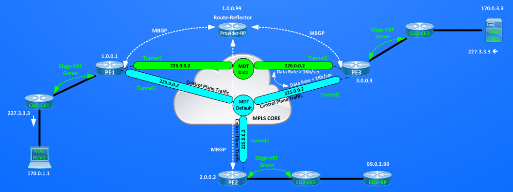
Now it’s time to activate MDT also for the second vrf VRF Black, I will use 225.0.0.1 as mdt default group and 226.0.0.1 as mdt data group:
PE1#sh run vrf Black | b ip
ip vrf Black
rd 1:200
mdt default 225.0.0.1
mdt data 226.0.0.1 0.0.0.0 threshold 1
route-target export 1:200
route-target import 1:200
MDT creates a new Tunnel3 on PE1:
PE1#sh ip int br | b Tunnel
Tunnel0 20.0.11.254 YES unset up up ==> This is used to encapsulate Register Message in Global IP toward Provider-RP for directly connected sources
Tunnel1 1.0.0.1 YES unset up up ==> This is used by MDT to tunnel Multicast VRF inside MDT-Group 225.0.0.2 for VRF Green
Tunnel2 70.0.1.254 YES unset up up ==> This is used to encapsulate Register Message inside VRF Green toward CU2-RP (99.0.2.99)
Tunnel3 1.0.0.1 YES unset up up ==> This is used by MDT to tunnel Multicast VRF inside MDT-Group 225.0.0.1 for VRF Black.
PE2#sh run vrf Black | b ip
ip vrf Black
rd 1:201
mdt default 225.0.0.1
mdt data 226.0.0.1 0.0.0.0 threshold 1
route-target export 1:200
route-target import 1:200
PE2 builds a new Tunnel3 too:
PE2#show ip int br | b Tunnel
Tunnel0 20.0.32.2 YES unset up up ==> This is used to encapsulate Register Message in Global IP toward Provider-RP for directly connected sources
Tunnel1 2.0.0.2 YES unset up up ==> This is used by MDT to tunnel Multicast VRF inside MDT-Group 225.0.0.2 for VRF Green
Tunnel2 69.0.2.254 YES unset up up ==> This is used to encapsulate Register Message inside VRF Green toward CU2-RP (99.0.2.99)
Tunnel3 2.0.0.2 YES unset up up ==> This is used by MDT to tunnel Multicast VRF inside MDT-Group 225.0.0.1 for VRF Black.
PE3#sh run vrf Black | b ip
ip vrf Black
rd 1:202
mdt default 225.0.0.1
mdt data 226.0.0.1 0.0.0.0 threshold 1
route-target export 1:200
route-target import 1:200
Then I will activate link of CU1-RP distributing via MDT (tunnelling Auto-RP messages inside VRF Black) the identity of the Rendezvousz-Point of VRF Black (99.0.1.99)
CU1-RP(config)#int e0/0
CU1-RP(config-if)#no shut
Info about RP identity reaches remote routers inside VRF Black:
CU1-CE1#show ip pim rp mapping
PIM Group-to-RP Mappings
Group(s) 224.0.0.0/4
RP 99.0.1.99 (?), v2v1
Info source: 99.0.1.99 (?), elected via Auto-RP
Uptime: 00:01:10, expires: 00:02:48
CU1-CE3#show ip pim rp mapping
PIM Group-to-RP Mappings
Group(s) 224.0.0.0/4
RP 99.0.1.99 (?), v2v1
Info source: 99.0.1.99 (?), elected via Auto-RP
Uptime: 00:03:34, expires: 00:02:22
Now I can activate source and receivers in VRF Black, source will transmit to group 228.1.1.1:
CU1-SRC1#show run | b sla
ip sla auto discovery
ip sla 1
icmp-echo 228.1.1.1 source-ip 169.0.1.1
request-data-size 5000
threshold 1000
timeout 1000
frequency 1
ip sla schedule 1 life forever start-time now
CU1-CE1#sh run int Lo0 | b interface
interface Loopback0
ip address 99.0.0.1 255.255.255.255
ip pim sparse-mode
CU1-CE1#sh run | s ip pim register
ip pim register-source Loopback0
CU1-RCV3(config)#int e0/1
CU1-RCV3(config-if)#ip igmp join-group 228.1.1.1
It’s interesting to look at how many tunnels we have now that both VRFs have multicast source and receivers active:
PE1#show ip int br | b Tunnel
Tunnel0 20.0.11.254 YES unset up up ==> This is used to encapsulate Register Message in Global IP toward Provider-RP for directly connected sources
Tunnel1 1.0.0.1 YES unset up up ==> This is used by MDT to tunnel Multicast VRF inside MDT-Group 225.0.0.2 for VRF Green
Tunnel2 70.0.1.254 YES unset up up ==> This is used to encapsulate Register Message inside VRF Green toward CU2-RP (99.0.2.99)
Tunnel3 1.0.0.1 YES unset up up ==> This is used by MDT to tunnel Multicast VRF inside MDT-Group 225.0.0.1 for VRF Black.
Tunnel4 69.0.1.254 YES unset up up ==> This is used to encapsulate Register Message inside VRF Black toward CU1-RP (99.0.1.99)
I have 5 Tunnels on other two PEs too:
PE2#show ip int br | b Tunnel
Tunnel0 20.0.32.2 YES unset up up ==> This is used to encapsulate Register Message in Global IP toward Provider-RP for directly connected sources
Tunnel1 2.0.0.2 YES unset up up ==> This is used by MDT to tunnel Multicast VRF inside MDT-Group 225.0.0.2 for VRF Green
Tunnel2 69.0.2.254 YES unset up up ==> This is used to encapsulate Register Message inside VRF Green toward CU2-RP (99.0.2.99)
Tunnel3 2.0.0.2 YES unset up up ==> This is used by MDT to tunnel Multicast VRF inside MDT-Group 225.0.0.1 for VRF Black.
Tunnel4 70.0.2.254 YES unset up up ==> This is used to encapsulate Register Message inside VRF Black toward CU1-RP (99.0.1.99)
PE3#show ip int br | b Tunn
Tunnel0 20.0.23.3 YES unset up up ==> This is used to encapsulate Register Message in Global IP toward Provider-RP for directly connected sources
Tunnel1 3.0.0.3 YES unset up up ==> This is used by MDT to tunnel Multicast VRF inside MDT-Group 225.0.0.2 for VRF Green
Tunnel2 70.0.3.254 YES unset up up ==> This is used to encapsulate Register Message inside VRF Green toward CU2-RP (99.0.2.99)
Tunnel3 3.0.0.3 YES unset up up ==> This is used by MDT to tunnel Multicast VRF inside MDT-Group 225.0.0.1 for VRF Black.
Tunnel4 69.0.3.254 YES unset up up ==> This is used to encapsulate Register Message inside VRF Black toward CU1-RP (99.0.1.99)
####### NOTE #######
To replicate this same order of Tunnels association you need to do this starting with all router down and with no mdt configuration.
1) Activate routers in Service Provider Network (Provider-RP, P routers and PE routers) configure PIM and Auto-RP features, this will enable Tunnel0 (and Tu1 on Provider-RP)
2) Configure mdt (default and data) for VRF Green on all PEs, this will enable Tunnel1 on all PEs
3) Activate CU2-RP, Auto-RP feature inside VRF Green will create via MDT Tunnel2 on all PEs
4) Configure mdt (default and data) for VRF Black on all PEs, this will enable Tunnel3 on all PEs
5) Activate CU1-RP, Auto-RP feature inside VRF Green will create via MDT Tunnel4 on all PEs
####### END NOTE ####
AS final test for now let’s verifiy that the last-hop routers connected to the receivers are forwarding multicast flow coming from the sources, look at counters incrementing
CU1-CE3#show ip mroute 228.1.1.1 count ==> VRF Black
Load for five secs: 0%/0%; one minute: 0%; five minutes: 0%
Time source is hardware calendar, *10:00:37.408 UTC Fri Nov 13 2015
Use “show ip mfib count” to get better response time for a large number of mroutes.
IP Multicast Statistics
4 routes using 1898 bytes of memory
2 groups, 1.00 average sources per group
Forwarding Counts: Pkt Count/Pkts per second/Avg Pkt Size/Kilobits per second
Other counts: Total/RPF failed/Other drops(OIF-null, rate-limit etc)
Group: 228.1.1.1, Source count: 1, Packets forwarded: 561, Packets received: 561
RP-tree: Forwarding: 0/0/0/0, Other: 0/0/0
Source: 169.0.1.1/32, Forwarding: 561/5/1023/41, Other: 561/0/0
CU1-CE3#show ip mroute 228.1.1.1 count
Load for five secs: 0%/0%; one minute: 0%; five minutes: 0%
Time source is hardware calendar, *10:00:42.136 UTC Fri Nov 13 2015
Use “show ip mfib count” to get better response time for a large number of mroutes.
IP Multicast Statistics
4 routes using 1898 bytes of memory
2 groups, 1.00 average sources per group
Forwarding Counts: Pkt Count/Pkts per second/Avg Pkt Size/Kilobits per second
Other counts: Total/RPF failed/Other drops(OIF-null, rate-limit etc)
Group: 228.1.1.1, Source count: 1, Packets forwarded: 586, Packets received: 586
RP-tree: Forwarding: 0/0/0/0, Other: 0/0/0
Source: 169.0.1.1/32, Forwarding: 586/5/1023/41, Other: 586/0/0
CU2-CE1#show ip mroute 227.3.3.3 count ==> VRF Green
Use “show ip mfib count” to get better response time for a large number of mroutes.
IP Multicast Statistics
4 routes using 2246 bytes of memory
2 groups, 1.00 average sources per group
Forwarding Counts: Pkt Count/Pkts per second/Avg Pkt Size/Kilobits per second
Other counts: Total/RPF failed/Other drops(OIF-null, rate-limit etc)
Group: 227.3.3.3, Source count: 1, Packets forwarded: 685, Packets received: 685
RP-tree: Forwarding: 0/0/0/0, Other: 0/0/0
Source: 170.0.3.3/32, Forwarding: 685/4/1133/41, Other: 685/0/0
CU2-CE1#show ip mroute 227.3.3.3 count
Load for five secs: 0%/0%; one minute: 0%; five minutes: 0%
Time source is hardware calendar, *10:02:11.749 UTC Fri Nov 13 2015
Use “show ip mfib count” to get better response time for a large number of mroutes.
IP Multicast Statistics
4 routes using 2246 bytes of memory
2 groups, 1.00 average sources per group
Forwarding Counts: Pkt Count/Pkts per second/Avg Pkt Size/Kilobits per second
Other counts: Total/RPF failed/Other drops(OIF-null, rate-limit etc)
Group: 227.3.3.3, Source count: 1, Packets forwarded: 851, Packets received: 851
RP-tree: Forwarding: 0/0/0/0, Other: 0/0/0
Source: 170.0.3.3/32, Forwarding: 851/4/1135/41, Other: 851/0/0
CU1-SRC1#ping 228.1.1.1
Type escape sequence to abort.
Sending 1, 100-byte ICMP Echos to 228.1.1.1, timeout is 2 seconds:
Reply to request 0 from 169.0.3.3, 2 ms <== CU1-RCV3 replies to multicast ping confirming things are ok.
CU2-SRC3#ping 227.3.3.3
Type escape sequence to abort.
Sending 1, 100-byte ICMP Echos to 227.3.3.3, timeout is 2 seconds:
Reply to request 0 from 170.0.1.1, 2 ms <== CU2-RCV1 replies to multicast ping confirming things are ok.
It’s time to recap with a picture what I set up:
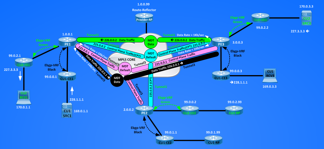
The picture above should help to see that for each VRF supporting multicast traffic I have two multicast groups active in the Core, on the MDT Default Group all PEs servicing the VRF will be active in a bidirectional way (as sources and as receivers of control plane traffic), on the MDT Data Group I will find only PEs that are Tunneling original multicast traffic coming from the sources (sending PEs) and PEs that has active receivers inside the VRFs (receiving PEs).
Here there are some useful commands to check if a PEs has active source or active receivers:
For VRF Black, PE1 is the sending PE whilw PE3 is receiving PE:
PE1#show ip mroute 226.0.0.1 | b \(
(*, 226.0.0.1), 04:12:18/stopped, RP 1.0.0.99, flags: SPFz
Incoming interface: Ethernet0/3, RPF nbr 20.0.11.1
Outgoing interface list: Null
(1.0.0.1, 226.0.0.1), 04:12:15/00:03:15, flags: FTz ==> F=Registered Source, T=Switched on Source Tree, z=MDT-data group sender
Incoming interface: Loopback0, RPF nbr 0.0.0.0
Outgoing interface list:
Ethernet0/3, Forward/Sparse-Dense, 04:12:15/00:02:56
PE1#show ip pim vrf Black mdt send
MDT-data send list for VRF: Black
(source, group) MDT-data group/num ref_count
(169.0.1.1, 228.1.1.1) 226.0.0.1 1 <== (Original Multicast Group (228.1.1.1) is Tunnelled inside MDT-data-group 226.0.0.1
PE3#show ip mroute 226.0.0.1 | b \(
(*, 226.0.0.1), 04:21:24/stopped, RP 1.0.0.99, flags: SJCZ ==> S=Sparse Mode, J=Rate is higher than SPT threshold (switch to SPT (flag T)), C=we have receivers directly connected
Incoming interface: Ethernet0/3, RPF nbr 20.0.23.2 ==> Z=Multicast Tunnel
Outgoing interface list:
MVRF Black, Forward/Sparse-Dense, 04:21:24/00:02:35
(1.0.0.1, 226.0.0.1), 04:21:21/00:02:59, flags: JTZ ==> J=Monitor rate of the source if < SPT-Threshold switch back to RPT, T=Switched on Source Tree, Z=Multicast Tunnel
Incoming interface: Ethernet0/3, RPF nbr 20.0.23.2
Outgoing interface list:
MVRF Black, Forward/Sparse-Dense, 04:21:21/00:02:38
PE3#show ip pim vrf Black mdt receive
Joined MDT-data [group/mdt number : source] uptime/expires for VRF: Black
[226.0.0.1 : 1.0.0.1] 04:18:50/00:02:09
PE3#show ip pim vrf Black mdt receive detail
Flags: D – Dense, S – Sparse, B – Bidir Group, s – SSM Group, C – Connected,
L – Local, P – Pruned, R – RP-bit set, F – Register flag,
T – SPT-bit set, J – Join SPT, M – MSDP created entry, E – Extranet,
X – Proxy Join Timer Running, A – Candidate for MSDP Advertisement,
U – URD, I – Received Source Specific Host Report,
Z – Multicast Tunnel, z – MDT-data group sender,
Y – Joined MDT-data group, y – Sending to MDT-data group,
G – Received BGP C-Mroute, g – Sent BGP C-Mroute,
N – Received BGP Shared-Tree Prune, n – BGP C-Mroute suppressed,
Q – Received BGP S-A Route, q – Sent BGP S-A Route,
V – RD & Vector, v – Vector, p – PIM Joins on route
Joined MDT-data [group/mdt number : source] uptime/expires for VRF: Black
[226.0.0.1 : 1.0.0.1] 04:19:13/00:02:46
(169.0.1.1, 228.1.1.1), 04:19:15/00:01:37/00:02:46, OIF count: 1, flags: TY
Similar outputs will result for VRF Green inverting roles between PE1 and PE3.
Let’s move forward with this Multicast Service Provider Example, I activated only one source per VRF so far, what happens if new source transmitting to new multicast group will be active inside the two VRFs? For simplicity I will use the same hosts for tranmitting to new groups configuring different sla probes. Below topology showing new active source and joined groups by receivers:
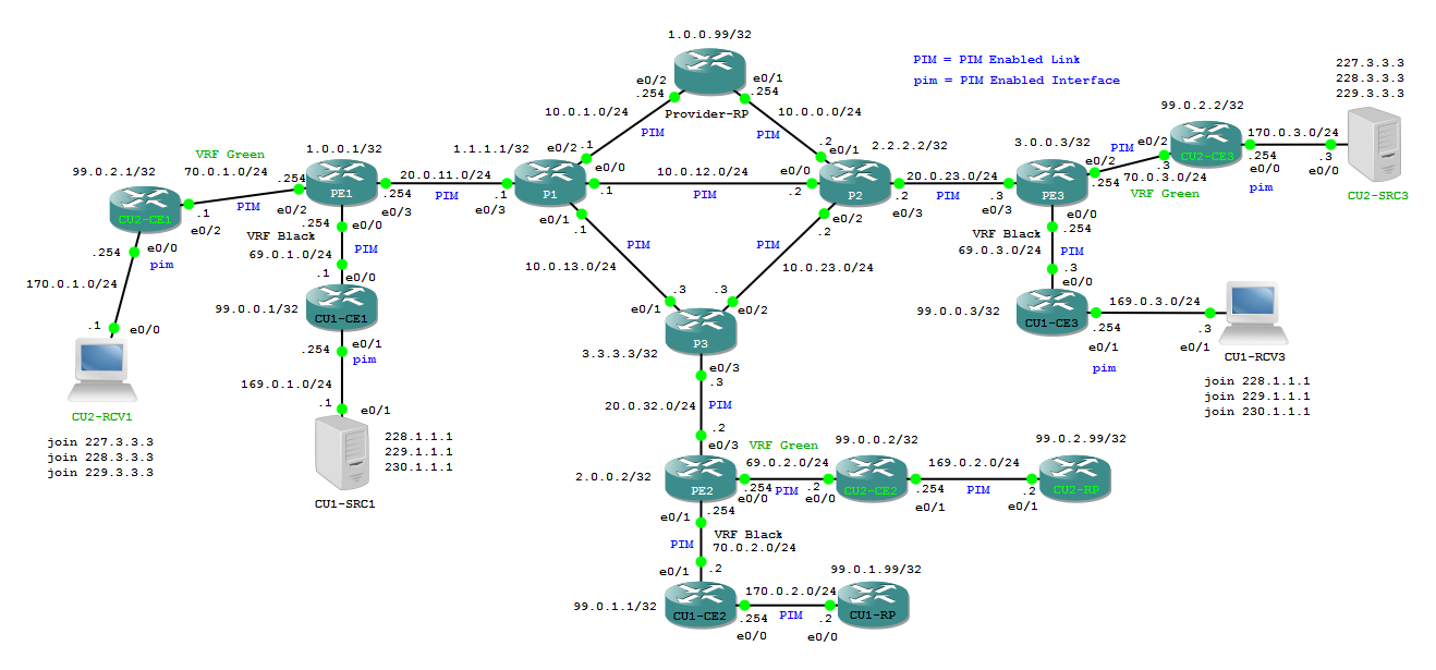 Here the result of activating new multicast groups on the first hop routers connected to Receivers:
CU1-CE3#show ip mroute | b \(
(*, 230.1.1.1), 00:10:23/stopped, RP 99.0.1.99, flags: SJC
Incoming interface: Ethernet0/0, RPF nbr 69.0.3.254
Outgoing interface list:
Ethernet0/1, Forward/Sparse, 00:10:23/00:02:38
(169.0.1.1, 230.1.1.1), 00:10:22/00:02:23, flags: JT
Incoming interface: Ethernet0/0, RPF nbr 69.0.3.254
Outgoing interface list:
Ethernet0/1, Forward/Sparse, 00:10:22/00:02:38
(*, 229.1.1.1), 00:10:28/stopped, RP 99.0.1.99, flags: SJC
Incoming interface: Ethernet0/0, RPF nbr 69.0.3.254
Outgoing interface list:
Ethernet0/1, Forward/Sparse, 00:10:28/00:02:33
(169.0.1.1, 229.1.1.1), 00:10:26/00:02:26, flags: JT
Incoming interface: Ethernet0/0, RPF nbr 69.0.3.254
Outgoing interface list:
Ethernet0/1, Forward/Sparse, 00:10:26/00:02:33
(*, 228.1.1.1), 05:16:32/stopped, RP 99.0.1.99, flags: SJC
Incoming interface: Ethernet0/0, RPF nbr 69.0.3.254
Outgoing interface list:
Ethernet0/1, Forward/Sparse, 05:16:32/00:02:29
(169.0.1.1, 228.1.1.1), 05:12:18/00:01:55, flags: JT
Incoming interface: Ethernet0/0, RPF nbr 69.0.3.254
Outgoing interface list:
Ethernet0/1, Forward/Sparse, 05:12:18/00:02:29
(*, 224.0.1.40), 05:16:33/stopped, RP 0.0.0.0, flags: DCL
Incoming interface: Null, RPF nbr 0.0.0.0
Outgoing interface list:
Ethernet0/0, Forward/Sparse-Dense, 05:16:33/stopped
(99.0.1.99, 224.0.1.40), 05:15:37/00:02:58, flags: PLT
Incoming interface: Ethernet0/0, RPF nbr 69.0.3.254
Outgoing interface list: Null
CU2-CE1#sh ip mroute | b \(
(*, 229.3.3.3), 00:02:37/stopped, RP 99.0.2.99, flags: SJC
Incoming interface: Ethernet0/2, RPF nbr 70.0.1.254
Outgoing interface list:
Ethernet0/0, Forward/Sparse, 00:02:37/00:02:36
(170.0.3.3, 229.3.3.3), 00:02:37/00:00:22, flags: JT
Incoming interface: Ethernet0/2, RPF nbr 70.0.1.254
Outgoing interface list:
Ethernet0/0, Forward/Sparse, 00:02:37/00:02:36
(*, 228.3.3.3), 00:02:42/stopped, RP 99.0.2.99, flags: SJC
Incoming interface: Ethernet0/2, RPF nbr 70.0.1.254
Outgoing interface list:
Ethernet0/0, Forward/Sparse, 00:02:42/00:02:33
(170.0.3.3, 228.3.3.3), 00:02:40/00:00:19, flags: JT
Incoming interface: Ethernet0/2, RPF nbr 70.0.1.254
Outgoing interface list:
Ethernet0/0, Forward/Sparse, 00:02:40/00:02:33
(*, 227.3.3.3), 05:17:31/stopped, RP 99.0.2.99, flags: SJC
Incoming interface: Ethernet0/2, RPF nbr 70.0.1.254
Outgoing interface list:
Ethernet0/0, Forward/Sparse, 05:17:31/00:02:37
(170.0.3.3, 227.3.3.3), 05:12:57/00:01:25, flags: JT
Incoming interface: Ethernet0/2, RPF nbr 70.0.1.254
Outgoing interface list:
Ethernet0/0, Forward/Sparse, 05:12:57/00:02:37
(*, 224.0.1.40), 05:17:32/stopped, RP 0.0.0.0, flags: DCL
Incoming interface: Null, RPF nbr 0.0.0.0
Outgoing interface list:
Ethernet0/2, Forward/Sparse-Dense, 05:17:30/stopped
Ethernet0/0, Forward/Sparse, 05:17:32/stopped
(99.0.2.99, 224.0.1.40), 05:16:44/00:02:38, flags: LT
Incoming interface: Ethernet0/2, RPF nbr 70.0.1.254
Outgoing interface list:
Ethernet0/0, Forward/Sparse, 05:16:44/stopped
Pinging multicast groups from sources confirms multicast is correctly delivered:
CU1-SRC1#ping 228.1.1.1
Type escape sequence to abort.
Sending 1, 100-byte ICMP Echos to 228.1.1.1, timeout is 2 seconds:
Reply to request 0 from 169.0.3.3, 1 ms
CU1-SRC1#ping 229.1.1.1
Type escape sequence to abort.
Sending 1, 100-byte ICMP Echos to 229.1.1.1, timeout is 2 seconds:
Reply to request 0 from 169.0.3.3, 2 ms
CU1-SRC1#ping 230.1.1.1
Type escape sequence to abort.
Sending 1, 100-byte ICMP Echos to 230.1.1.1, timeout is 2 seconds:
Reply to request 0 from 169.0.3.3, 2 ms
CU2-SRC3#ping 227.3.3.3
Type escape sequence to abort.
Sending 1, 100-byte ICMP Echos to 227.3.3.3, timeout is 2 seconds:
Reply to request 0 from 170.0.1.1, 1 ms
CU2-SRC3#ping 228.3.3.3
Type escape sequence to abort.
Sending 1, 100-byte ICMP Echos to 228.3.3.3, timeout is 2 seconds:
Reply to request 0 from 170.0.1.1, 6 ms
CU2-SRC3#ping 229.3.3.3
Type escape sequence to abort.
Sending 1, 100-byte ICMP Echos to 229.3.3.3, timeout is 2 seconds:
Reply to request 0 from 170.0.1.1, 4 ms
PE1#show ip pim vrf Black mdt send ==> 3 groups tunnelled inside one MDT data group.
MDT-data send list for VRF: Black
(source, group) MDT-data group/num ref_count
(169.0.1.1, 228.1.1.1) 226.0.0.1 3
(169.0.1.1, 229.1.1.1) 226.0.0.1 3
(169.0.1.1, 230.1.1.1) 226.0.0.1 3
PE3#show ip pim vrf Black mdt receive detail | b uptime
Joined MDT-data [group/mdt number : source] uptime/expires for VRF: Black
[226.0.0.1 : 1.0.0.1] 05:39:05/00:02:54
(169.0.1.1, 228.1.1.1), 05:39:07/00:01:38/00:02:54, OIF count: 1, flags: TY
(169.0.1.1, 229.1.1.1), 00:37:16/00:01:57/00:02:54, OIF count: 1, flags: TY
(169.0.1.1, 230.1.1.1), 00:37:12/00:02:06/00:02:54, OIF count: 1, flags: TY
PE3#show ip pim vrf Green mdt send ==> 3 groups tunnelled inside one MDT data group.
MDT-data send list for VRF: Green
(source, group) MDT-data group/num ref_count
(170.0.3.3, 227.3.3.3) 226.0.0.2 3
(170.0.3.3, 228.3.3.3) 226.0.0.2 3
(170.0.3.3, 229.3.3.3) 226.0.0.2 3
PE1#show ip pim vrf Green mdt receive detail | b uptime
Joined MDT-data [group/mdt number : source] uptime/expires for VRF: Green
[226.0.0.2 : 3.0.0.3] 05:40:02/00:02:57
(170.0.3.3, 227.3.3.3), 05:40:05/00:02:36/00:02:57, OIF count: 1, flags: TY
(170.0.3.3, 228.3.3.3), 00:29:49/00:01:36/00:02:57, OIF count: 1, flags: TY
(170.0.3.3, 229.3.3.3), 00:29:46/00:01:35/00:02:57, OIF count: 1, flags: TY
Now let’s consider what does mean activating new sources in the same VRFs or new sources in new VRFs:
The more loaded routers from multicast resources usage point of view are the PE routers, PE must maintain Multicast VRF routing Table and Multicast Global IP routing Tables.
– For each new source inside an existing VRF a PE will install a multicast (*,G) and (S,G) entry for the new group in mVRF Routing Table.
– For each new source inside a new VRF a PE will install a multicast (*,G) and (S,G) entry for the new group in mVRF Routing Table and
– ONE new (*,G) entry for the MDT default group and M new (S,G) entries for the MDT default group, where M is the number of PEs
– ONE new (*,G) and ONE new (S,G) entry for the MDT data group that PE is using to trasnmit the new source
– N new (*,G) and N new (S,G) entry for the MDT data group that PE is using to receive from other N PEs that are sending on data group where this PEs has active receivers on.
Similar resources will be used by PE with active receivers in the VRFs.
For example I look at MRIBs of PE1:

I see in the Global IP Multicast routing table:
# one (*,225.0.0.1) and three (1.0.0.1,225.0.0.1) – (2.0.0.2,225.0.0.1) – (3.0.0.3,225.0.0.1)
# one (*,225.0.0.2) and three (1.0.0.1,225.0.0.2) – (2.0.0.2,225.0.0.2) – (3.0.0.3,225.0.0.2)
# one (*,226.0.0.1) and one (1.0.0.1,226.0.0.1)
# one (*,226.0.0.2) and one (3.0.0.3,226.0.0.2)
the same multicast entries will be present on P routers, for example on P1:
P1#show ip mroute | b \(
(*, 226.0.0.1), 02:04:04/stopped, RP 1.0.0.99, flags: SP
Incoming interface: Ethernet0/2, RPF nbr 10.0.1.254
Outgoing interface list: Null
(1.0.0.1, 226.0.0.1), 02:04:04/00:03:03, flags: T
Incoming interface: Ethernet0/3, RPF nbr 20.0.11.254
Outgoing interface list:
Ethernet0/0, Forward/Sparse-Dense, 02:04:04/00:03:27
(*, 226.0.0.2), 02:04:07/00:02:32, RP 1.0.0.99, flags: S
Incoming interface: Ethernet0/2, RPF nbr 10.0.1.254
Outgoing interface list:
Ethernet0/3, Forward/Sparse-Dense, 02:04:07/00:02:32
(3.0.0.3, 226.0.0.2), 02:04:03/00:03:14, flags: T
Incoming interface: Ethernet0/0, RPF nbr 10.0.12.2
Outgoing interface list:
Ethernet0/3, Forward/Sparse-Dense, 02:04:03/00:03:22
(*, 225.0.0.1), 02:05:10/00:03:21, RP 1.0.0.99, flags: S
Incoming interface: Ethernet0/2, RPF nbr 10.0.1.254
Outgoing interface list:
Ethernet0/3, Forward/Sparse-Dense, 02:05:10/00:03:21
(3.0.0.3, 225.0.0.1), 02:05:10/00:02:23, flags: T
Incoming interface: Ethernet0/0, RPF nbr 10.0.12.2
Outgoing interface list:
Ethernet0/3, Forward/Sparse-Dense, 02:05:10/00:03:21
(2.0.0.2, 225.0.0.1), 02:05:10/00:02:12, flags: T
Incoming interface: Ethernet0/1, RPF nbr 10.0.13.3
Outgoing interface list:
Ethernet0/3, Forward/Sparse-Dense, 02:05:10/00:03:21
(1.0.0.1, 225.0.0.1), 02:05:10/00:02:12, flags: T
Incoming interface: Ethernet0/3, RPF nbr 20.0.11.254
Outgoing interface list:
Ethernet0/0, Forward/Sparse-Dense, 02:05:09/00:03:12
Ethernet0/1, Forward/Sparse-Dense, 02:05:09/00:03:20
(*, 225.0.0.2), 02:05:10/00:03:24, RP 1.0.0.99, flags: S
Incoming interface: Ethernet0/2, RPF nbr 10.0.1.254
Outgoing interface list:
Ethernet0/3, Forward/Sparse-Dense, 02:05:10/00:03:24
(3.0.0.3, 225.0.0.2), 02:05:10/00:02:13, flags: T
Incoming interface: Ethernet0/0, RPF nbr 10.0.12.2
Outgoing interface list:
Ethernet0/3, Forward/Sparse-Dense, 02:05:10/00:03:24
(2.0.0.2, 225.0.0.2), 02:05:10/00:02:16, flags: T
Incoming interface: Ethernet0/1, RPF nbr 10.0.13.3
Outgoing interface list:
Ethernet0/3, Forward/Sparse-Dense, 02:05:10/00:03:24
(1.0.0.1, 225.0.0.2), 02:05:10/00:02:16, flags: T
Incoming interface: Ethernet0/3, RPF nbr 20.0.11.254
Outgoing interface list:
Ethernet0/0, Forward/Sparse-Dense, 02:05:09/00:03:20
Ethernet0/1, Forward/Sparse-Dense, 02:05:09/00:03:11
(*, 224.0.1.39), 02:07:11/stopped, RP 0.0.0.0, flags: DC
Incoming interface: Null, RPF nbr 0.0.0.0
Outgoing interface list:
Ethernet0/3, Forward/Sparse-Dense, 02:06:41/stopped
Ethernet0/0, Forward/Sparse-Dense, 02:06:42/stopped
Ethernet0/1, Forward/Sparse-Dense, 02:06:42/stopped
Ethernet0/2, Forward/Sparse-Dense, 02:07:11/stopped
(1.0.0.99, 224.0.1.39), 02:06:11/00:02:43, flags: PT
Incoming interface: Ethernet0/2, RPF nbr 10.0.1.254
Outgoing interface list:
Ethernet0/1, Prune/Sparse-Dense, 02:06:11/00:00:44, A
Ethernet0/0, Prune/Sparse-Dense, 02:06:11/00:00:44
Ethernet0/3, Prune/Sparse-Dense, 00:00:11/00:02:48
(*, 224.0.1.40), 02:07:11/stopped, RP 0.0.0.0, flags: DCL
Incoming interface: Null, RPF nbr 0.0.0.0
Outgoing interface list:
Ethernet0/2, Forward/Sparse-Dense, 02:06:41/stopped
Ethernet0/3, Forward/Sparse-Dense, 02:06:41/stopped
Ethernet0/1, Forward/Sparse-Dense, 02:07:11/stopped
Ethernet0/0, Forward/Sparse-Dense, 02:07:11/stopped
(1.0.0.99, 224.0.1.40), 02:06:11/00:02:40, flags: LT
Incoming interface: Ethernet0/2, RPF nbr 10.0.1.254
Outgoing interface list:
Ethernet0/0, Prune/Sparse-Dense, 02:06:11/00:00:44
Ethernet0/1, Forward/Sparse-Dense, 02:06:11/stopped, A
Ethernet0/3, Forward/Sparse-Dense, 02:06:11/stopped
The advantage of using MDT is that Multicast info of serviced customers will not be present on core routers of the Service Provider and a Customer it’s free to deploy multicast service inside its network, putting Rendezvousz-Point wherever they want and activating sources, without impacting on the multicast routing table of the P core routers of the Service Provider.
Considering the scalability of this solution we can say that the MDT defult groups has the higher impact, because all PEs that have the same VRFs configured will join this group sending and receiving control traffic for this group.
Service Provider can optimize this exchange of control traffic take advantage of the fact that each PE on the MDT defaul group is acting as sender and receiver so this exchange of information is naturally bidirectional. Service Provider can then uses BIDIRECTIONAL PIM to speak multicast on the MDT default groups.
As last example I will configure bidirectional PIM for the MDT default groups 225.0.0.1 and 225.0.0.2, before doing that I will stop all source and recivers and I clean all MRIBs restarting from a clean condition.
I modify the configuration on Provider-RP in this way:
I add Loopback1 1.0.0.100 to distinguish the RP for bidiriectional groups.
Provider-RP#sh run int Lo1 | b interface
interface Loopback1
ip address 1.0.0.100 255.255.255.255
ip pim sparse-dense-mode
Provider-RP#sh run | s rp-
ip pim send-rp-announce Loopback1 scope 255 group-list 1
ip pim send-rp-announce Loopback0 scope 255 group-list 99 bidir
ip pim send-rp-discovery scope 255 <== here I’m using ethernet interfaces as Auto-RP discovery interfaces:
Provider-RP#show ip mroute 224.0.1.40 | b \(
(*, 224.0.1.40), 02:32:04/stopped, RP 0.0.0.0, flags: DCL
Incoming interface: Null, RPF nbr 0.0.0.0
Outgoing interface list:
Ethernet0/2, Forward/Sparse-Dense, 02:29:09/stopped
Ethernet0/1, Forward/Sparse-Dense, 02:29:09/stopped
Loopback1, Forward/Sparse-Dense, 02:32:04/stopped
(10.0.1.254, 224.0.1.40), 00:00:22/00:02:37, flags: LT
Incoming interface: Ethernet0/2, RPF nbr 0.0.0.0
Outgoing interface list:
Loopback1, Forward/Sparse-Dense, 00:00:22/stopped
Ethernet0/1, Prune/Sparse-Dense, 00:00:22/00:02:37, A
(10.0.0.254, 224.0.1.40), 00:00:22/00:02:37, flags: LT
Incoming interface: Ethernet0/1, RPF nbr 0.0.0.0
Outgoing interface list:
Loopback1, Forward/Sparse-Dense, 00:00:22/stopped
Ethernet0/2, Prune/Sparse-Dense, 00:00:22/00:02:37, A
Provider-RP#sh run | s access
access-list 1 permit 226.0.0.2
access-list 1 permit 226.0.0.1
access-list 99 permit 225.0.0.1 ==> bidirectional PIM group
access-list 99 permit 225.0.0.2 ==> bidirectional PIM group
Now I have 1.0.0.99 as Rendezvousz-Point for MDT Default-Group 225.0.0.1 and 225.0.0.2 working in bidiriectional-PIM, and 1.0.0.100 for MDT-Data-Group 226.0.0.1 and 226.0.0.2 working in normal PIM Sparse Mode.
Rendezvousz-Point identities are correctly distributed to all Core routers:

Then I activate again MDT in both VRFs Green and Black (configuration doesn’t change for the VRFs commands are still mdt default… and mdt data…), then testing multicast traffic confirms that multicast flow is correctly delivered:
CU1-SRC1#ping 228.1.1.1
Type escape sequence to abort.
Sending 1, 100-byte ICMP Echos to 228.1.1.1, timeout is 2 seconds:
Reply to request 0 from 169.0.3.3, 6 ms
CU1-SRC1#ping 229.1.1.1
Type escape sequence to abort.
Sending 1, 100-byte ICMP Echos to 229.1.1.1, timeout is 2 seconds:
Reply to request 0 from 169.0.3.3, 8 ms
CU1-SRC1#ping 230.1.1.1
Type escape sequence to abort.
Sending 1, 100-byte ICMP Echos to 230.1.1.1, timeout is 2 seconds:
Reply to request 0 from 169.0.3.3, 3 ms
CU2-SRC3#ping 227.3.3.3
Type escape sequence to abort.
Sending 1, 100-byte ICMP Echos to 227.3.3.3, timeout is 2 seconds:
Reply to request 0 from 170.0.1.1, 11 ms
CU2-SRC3#ping 228.3.3.3
Type escape sequence to abort.
Sending 1, 100-byte ICMP Echos to 228.3.3.3, timeout is 2 seconds:
Reply to request 0 from 170.0.1.1, 5 ms
CU2-SRC3#ping 229.3.3.3
Type escape sequence to abort.
Sending 1, 100-byte ICMP Echos to 229.3.3.3, timeout is 2 seconds:
Reply to request 0 from 170.0.1.1, 1 ms
The advantage of configuring MDT-Default-Group in Bidirectional Mode is that we can save the space the multicast entries (S,G) would occupy in the MRIB of the P and PE routers:
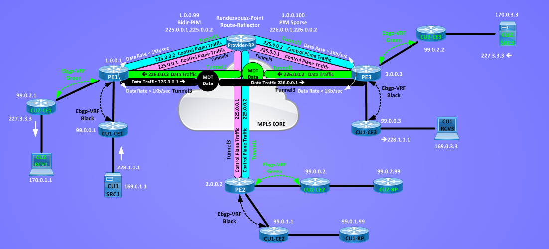
With PIM-Bidir Proivder-RP will be in the data-plane for the MDT-Default-Group, the following picture compares multicast routing table of PE1 without and with MDT default groups working in bidirectional mode:

I saved 6 = 3 (number of PEs) x 2 (number of MDT Default Groups) (S,G) entries in MRIB, if many PEs are active in the network and many VRFs are active on each PEs, we can save a lot of multicast resources in the core routers.
Here a zip file with final config from all routers:
REFERENCE:
“Developing IP Multicast Network”
“MPLS and VPN Architectures, Volume II”
Other Multicast Links