In the first part of the post I reviewed a Multicast VPN scenario where multicast traffic of the customer is tunneled under PIM MDT mGRE Tunnels inside the core of the Service Provider; after PIM MDT in the core is converged, the resulting effect on the network is to have mGRE P-Tunnels (Provider Multicast Service Interface – PMSI in RFC6388) where each PE can send its data and the same data can be received by other PEs at the remote ends of these Tunnels, the following figure should show the concept:
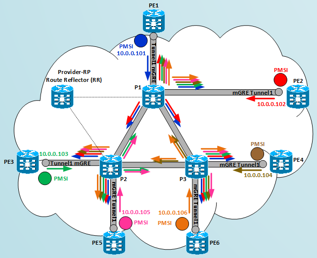
Now, forget for a moment how PIM/MDT have built the trees, the final result is that we have in the core six multipaths rooted at each PEs where you can inject data received from the customers and these data will be delivered to all remote PEs that joined the multi-tree. Let’s now abstract the data plane operations when a multicast packet of the customer is received by one PE and delivered to other remote PEs through the tree built in the core. PE6 receives the packet from the source connected to CE6 on its vrf interface, PE6 is the service router where some forwarding instructions is attached to the packet in such a way that the packet can reach all the interested receivers, which is this instruction that once attached to the packet let us get this result? What PE6 must do is to add the mGRE Tunnel1 encapsulation [10.0.0.106, 239.1.1.1] to the packet and then sending the encapsulated packet out of its outgoing interfaces as established by the multicast entries (10.0.0.106,239.1.1.1) inside its global mrib; other routers of the network, especially the P routers inside the core, has already programmed their structure (thanks to PIM/MDT read the first part of the post for further details) to handle this packet, for example P3 knows that it must forward it out of three interfaces to reach PE4, P1 and P2, in the same way P1 and P2 will send this packet out from two interfaces to reach PE1, PE2 and PE3 and PE5 respectively. Leaving intact the multicast solution of the customer behind the VRFs, we can think to remove PIM from the core and use another method to program PEs and P routers with the right instructions to send the same multicast packets of the customer to remote PEs. This alternative solution is mLDP.
Before moving to see how mLDP works, let’s review how “normal” LDP works in establishing Multipoint-to-Point (MP2P) Label Switched Paths (LSPs)
Below you can see the same topology I used in the first part of the post:
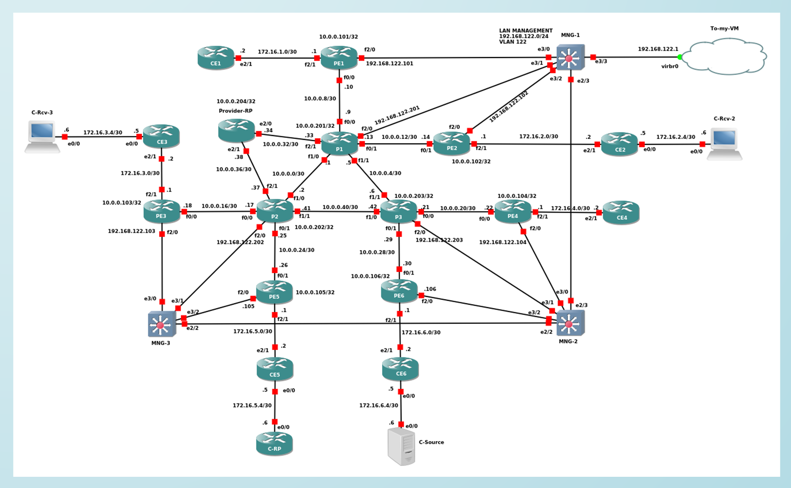
Focus on Ps and PEs network, switches are present as management connection toward my Ubuntu Virtual Machine because I used Ansible to automate the configuration of the nine routers. I used OSPF as IGP to connect P and PEs, and enabled LDP on all links, I constrained the label space on each router in such a way that is simple to look at the label and knowing who generated that label:
P1#show mpls label range
Downstream Generic label region: Min/Max label: 1000/1999
P2#show mpls label range
Downstream Generic label region: Min/Max label: 2000/2999
P3#show mpls label range
Downstream Generic label region: Min/Max label: 3000/3999
PE1#show mpls label range
Downstream Generic label region: Min/Max label: 10000/10999
PE2#show mpls label range
Downstream Generic label region: Min/Max label: 20000/20999
PE3#show mpls label range
Downstream Generic label region: Min/Max label: 30000/30999
PE4#show mpls label range
Downstream Generic label region: Min/Max label: 40000/40999
PE5#show mpls label range
Downstream Generic label region: Min/Max label: 50000/50999
PE6#show mpls label range
Downstream Generic label region: Min/Max label: 60000/60999
By default, LDP on Cisco router uses a Downstream Unsolicited method to distribute the labels, this means that as soon as connected routes and IGP learned routes are known to a router, it generates a label for each routes and send these labels to its LDP peers, without waiting for the peers asking for them. Downstream is the usual concept of “which is the next hop DOWN to the destination from my point of view?” For example, let’s consider only the loopback addresses and let’s see which are the Label Switched Paths from PE1 Lo0 10.0.0.101 to PE5 Lo0 10.0.0.105 and PE6 Lo0 10.0.0.106.
PE1#traceroute 10.0.0.105 source 10.0.0.101
Type escape sequence to abort.
Tracing the route to 10.0.0.105
1 10.0.0.9 [MPLS: Label 1011 Exp 0] 48 msec 16 msec 28 msec
2 10.0.0.2 [MPLS: Label 2011 Exp 0] 28 msec 32 msec 16 msec
3 10.0.0.26 48 msec 60 msec 60 msec
Traceroute shows me that the packet originated by PE1 and sent toward PE5 is switched using two labels 1011 and 2011, looking above at the label space imposed by each router it’s simple to see that the first label 1011 is imposed by P1 and the second label 2011 is imposed by P2, let’s follow the path starting from the destination point PE5:
PE5#show mpls ldp bindings local 10.0.0.105 32
lib entry: 10.0.0.105/32, rev 4
local binding: label: imp-null
This output tells me that PE5 imposes an implicit-null label to its connected loopback, in other words it tells its upstream ldp neighbor (the neighbor from which it could receive labeled packet for network 10.0.0.105/32) to perform Penultimate-Hop-Popping on the packet, that is, “Please P2 remove the top label from the packet when sending it to me”. Let’s move upstream toward the source of the packet, on P2 I see:
P2#show mpls forwarding-table 10.0.0.105 32
Local Outgoing Prefix Bytes Label Outgoing Next Hop
Label Label or Tunnel Id Switched interface
2011 Pop Label 10.0.0.105/32 672 Fa0/1 10.0.0.26
This output tells me two things:
1] that P2 locally assigns a label of 2011 to the FEC 10.0.0.105/32 (and it distributes this label to all its LDP peers, to PE5 too), in other words P2 tells all its LDP neighbors to use this 2011 label when sending to it packets directed to 10.0.0.0.105/32, but only its upstream neighbors (the ones for which it is a next-hop router to the destination of the packet – another way to see an upstream neighbor – in this case only P1) will really use it.
2] and that when it must send the packet down to the destination it must POP the label, that is, P2 removes the top label of the packet (in this case of simple IP/MPLS switching only one label is present, then P2 sends a pure ip packet to PE5) and this action was imposed by PE5. Let’s move on P1
P1#show mpls forwarding-table 10.0.0.105 32
Local Outgoing Prefix Bytes Label Outgoing Next Hop
Label Label or Tunnel Id Switched interface
1011 2011 10.0.0.105/32 360 Fa1/0 10.0.0.2
This output tells me that P1 assigns locally label 1011 to 10.0.0.105/32 and it distributes it to all its LDP peers, to PE1 and to P2 too, but only PE1 will use it when sending packets toward 10.0.0.105/32, because only for PE1 P1 it’s a next hop router for that network. P1 will use instead label 2011 (as imposed by P2) to send the packet out of interface Fa1/0 toward P2. Let’s move on the final upstream router PE1 where the packet originates:
PE1#show mpls forwarding-table 10.0.0.105 32
Local Outgoing Prefix Bytes Label Outgoing Next Hop
Label Label or Tunnel Id Switched interface
10014 1011 10.0.0.105/32 0 Fa0/0 10.0.0.9
A similar thing happens when PE1 sends a packet to PE6’s Lo0:
PE1#traceroute 10.0.0.106 source 10.0.0.101
Type escape sequence to abort.
Tracing the route to 10.0.0.106
1 10.0.0.9 [MPLS: Label 1010 Exp 0] 52 msec 12 msec 24 msec
2 10.0.0.6 [MPLS: Label 3011 Exp 0] 56 msec 28 msec 20 msec
3 10.0.0.30 24 msec 40 msec 28 msec
LDP LSPs are inherently unidirectional, and the data flow moves in the opposite direction of the one followed by the signaling of the labels, in other words, starting from the source node, at each hop, the label that must be used by the router to send the packet out of it, it is signaled by the downstream (next-hop router toward the destination) node. I can say that the LSP is rooted at the source node and made of a sequence of labels that are determined by the downstream hops in the path. If now I consider the return traffic coming and originated from PE5 and PE6 I need to view PE5 and PE6 as the new root node, and to determine the sequence of labels that must be used to send a packet from them to 10.0.0.101 I must start to look at the new destination node (PE1);
PE5#traceroute 10.0.0.101 source 10.0.0.105
Type escape sequence to abort.
Tracing the route to 10.0.0.101
1 10.0.0.25 [MPLS: Label 2007 Exp 0] 92 msec 40 msec 28 msec
2 10.0.0.1 [MPLS: Label 1006 Exp 0] 28 msec 48 msec 16 msec
3 10.0.0.10 44 msec 36 msec 24 msec
PE6#traceroute 10.0.0.101 source 10.0.0.106
Type escape sequence to abort.
Tracing the route to 10.0.0.101
1 10.0.0.29 [MPLS: Label 3007 Exp 0] 124 msec 64 msec 12 msec
2 10.0.0.5 [MPLS: Label 1006 Exp 0] 36 msec 12 msec 16 msec
3 10.0.0.10 28 msec 40 msec 36 msec
Let’s draw the built LSPs between PE1 and PE5 and PE6.
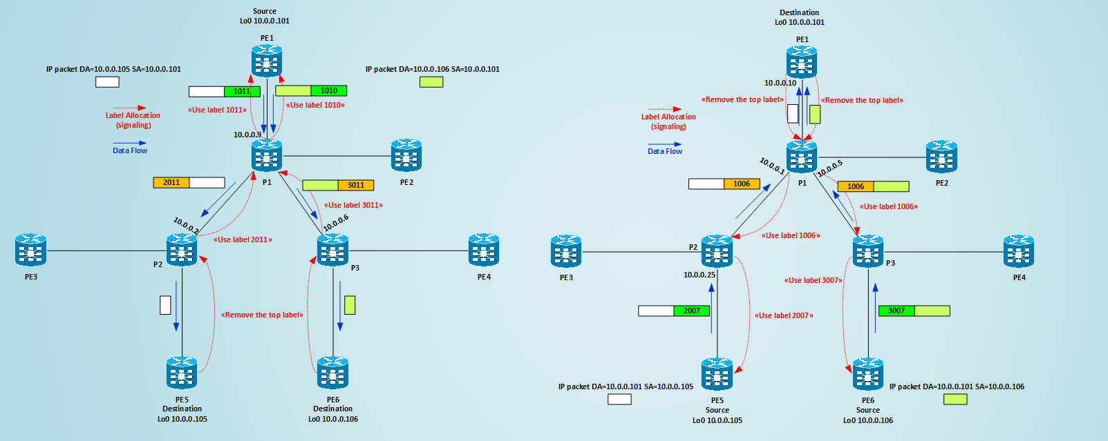
The picture should help you in visualizing the labels signaling flow and the data flow moving in opposite directions.
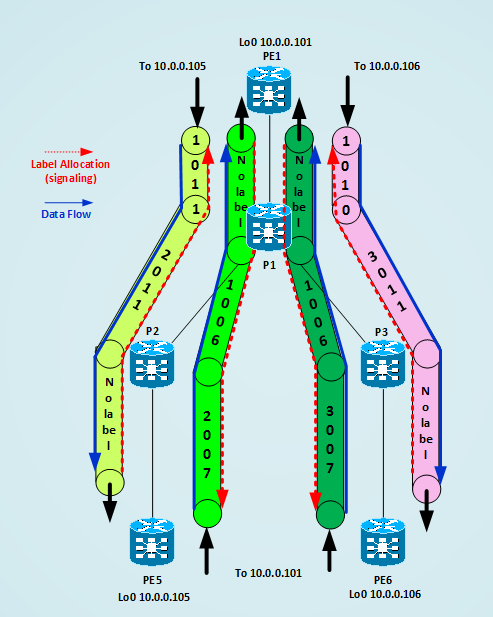
This other picture abstracts the previous one:
The picture summarizes what an LSP is, you can see that to have bidirectional connectivity between two nodes, through an MPLS path, we need two distinct LSPs that move traffic in opposite directions, using labels assigned by the downstream routers, the data flow and the label signaling have opposite directions, data flow moves from source to the destination, label signaling moves from destination (egress) node to source (ingress) node.
Now, in some references you can find surfing the web, you can read something like this: “LDP builds Multipoint to Point Label Switch Paths (MP2P LSPs)” that you can interpret also with something similar to “LDP builds LSPs that you can use as Many-to-One communication”. Where is this Many-to-One concept in the example above? You can see it more easily when looking traffic moving from PE5 and PE6 to PE1, in that case, you have two distinct unidirectional LSPs that “target” PE1, these LSPs are built from a signaling point of view starting from PE1, the egress PE, and hop by hop up to the source PEs (PE5 and PE6 in this case), all the process is driven by the fact that at each hop knowledge of route to PE1’s Loopback (10.0.0.101/32) generates a label locally and toward the upstream neighbors (to be precise to all neighbors, but only upstream neighbors will use it), in this sense you can view the LSPs as Multipoint to Point (MP2P) LSPs, in other words when the egress PE generates and advertises the label for a FEC, all other remote PEs – after labels are distributed hop-by-hop – can reach this FEC via an MPLS LSP. Next figure illustrates how at each hop routers that have a common downstream neighbor will use the same label to switch the packet toward the destination and that the building of the LSPs to reach the FEC originated by PE1 is started from PE1 itself, in this sense you can consider LDP LSPs MP2P paths, from any ingress PE you have one (or more based upon the topology) prebuilt LSP to reach the FEC on the egress PE. Despite of that concept I prefer to see each LSP signaled by LDP as Point-to-Point (P2P) LSP.
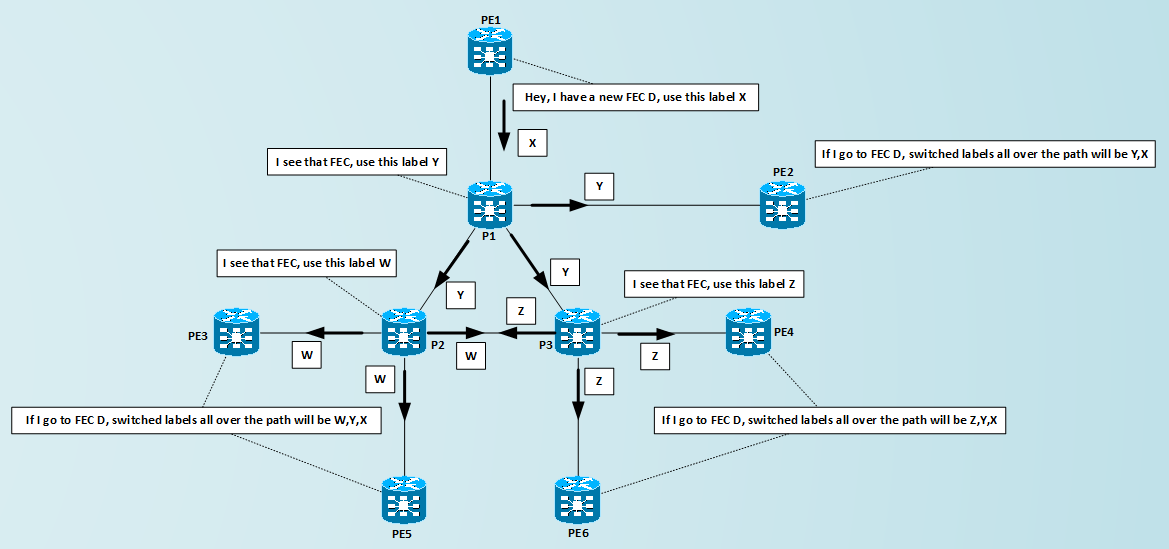
Here it’s worth to see that this happens for any FEC that an egress PE could originate, that is, for any FEC (prefix in this case) one label is generated and advertised, if PE1 is egress PE for ten FECs it generates and advertises ten different labels, the same happens at each hop, there is no aggregation of labels/FECs
Now, what all this LDP stuff has to do with mLDP? In my opinion nothing, but when I approached mLDP, in some reference I read that a MP2MP mLDP LSP can be seen as made of two parts: one Point-to-Multipoint (P2MP) Tree and one Multipoint-to-Point (MP2P) Tree, this is true, but the MP2P part must not be confused with the MP2P unicast LDP tree as I described above, of course this is a my opinion, this comparison should be clearer if you have the patience to read all the article.
Before moving on to see what an mLDP LSP path is, let’s spend last few words on how the labels are distributed by LDP, because this helps to understand better the extensions to LDP introduced to support mLDP. The process can be summarized as follows:
1] LDP peers discover each other using Hello messages.
2] Peers exchange Initialization Messages, in these meessages they try to agree about the features they can both support.
During these initialization messages Capabilities TLVs are exchanges. TLVs are messages formatted as Type, Length Value messages. Below you can find the initialization message sent by P1 to PE1:
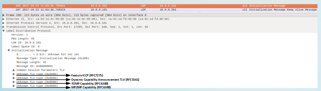
It’s possible to see how P1 sends some capability TLVs with the Unknown Bit (if the peer doesn’t know how to handle them, it can ignore them) set, among others we can see that types 0x0508 and 0x0509 are used to advertise the capability to support P2MP and MP2MP LSPs paths respectively. After becoming LDP peers, routers start to exchange the labels, to do that they use Forwarding Equivalent Class (FEC) Elements encoded as TLVs, together with Label TLVs, both things are sent in Label Mapping Messages. Here you can see one of this message sent by P1 to PE1:
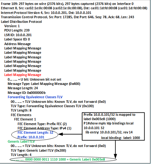
Now, similar elements (FEC elements inside label mapping messages) are used also in mLDP, but in mLDP a FEC is not a single prefix but a combination of 3 things:
- Tree Type
- Root Node Address
- Opaque Field (Variable Length)
below you can find a picture that describes it and that I did based on what is described in RFC6388:

There are three FEC types defined by mLDP, P2MP Fec Element (Type = 0x06), MP2MP Upstream FEC element (0x07), MP2MP Downstream FEC element (0x08), the Address Family field can identify IPv4 (value = 1) or IPv6 (Value = 2), address length is 32 or 128 based on ipv4 or ipv6 addresses, the Root Node Address is the address of the node where the mLDP LSP tree is rooted and is used to route the LSP through the network, the Opaque Value is used to identify the tree inside the MPLS network, it is encoded as a TLV structure and its value and encoding are defined by the application (for example MDTs Default/Data in a Multicast VPN) that uses the LSPs path created by mLDP.
Now, I’ve just reviewed what a P2P (a.k.a MP2P LSP) is, reading RFC6388 we can found theses definition for Multipoint LSPs:
A Point to Multipoint (P2MP) LSP can be seen like a tree where we have a single root, zero or more transit nodes, and one or more leaf nodes, all these nodes must do some operations from a signaling ad forwarding point of view that simplifying (and not considering that each node can have multiple roles) are:
- Leaf nodes initiate P2MP Signaling and install forwarding states to deliver traffic received on P2MP LSP to exit the tree
- Transit nodes propagate this signaling toward the root and install MPLS forwarding states to move traffic down to the leaves or to other transit nodes
- Root node install forwarding states to map the desired traffic into the P2MP LSP
The combination of [Root Address, Opaque Value] uniquely identifies a P2MP LSP in the network.
A Multipoint to Multipoint (MP2MP) LSP can be seen like a tree where nodes work as both root and leaves and where traffic can flow in a bidirectional way from the root to the leaves and from the leaves to the root. This type of LSP is made of two parts, one part is a P2MP LSP rooted at the shared root node (signaling data move from the leaves to the root, traffic data move from the root downstream to all the leaves in the opposite direction), the second part is a MP2P that starting from the leaves target the root node (signaling move from the root to all the leaves, traffic data move from the leaves upstream to the root, this is a simplification as you can see later on).
Now, reading these definitions and have well understood how a MDT Default group works using mGRE Tunnels, it should be easy to map the behavior of an MDT Default mGRE forwarding tunnel to an MP2MP LSP, the following figure shows the forwarding states built by PIM MDT Default group 239.1.1.1 for each PE working as a source (see the first part of the post for more details).
To remove PIM and substitute it with a MP2MP LSP I need something that builds the same forwarding states in the core and something that maps the traffic I need to send from a source PE to this MP2MP tree. Let’s try to build this tree step by step.
Step 1 – removing PIM protocol from the core
As said I don’t want to use PIM/mGRE to transport C-Multicast traffic, then I remove it from the network, I will clear PIM configurations on all the routers
Step3 – Remove mdt commands (used before to create the PIM/MDT group from the vrf) and BGP MDT address-family configuration where used before, configure the vrf (in this case only the one of my test) with a VPN Identifier
In the attached file you can see all the commands used to remove PIM from routers and their involved interfaces and the removing of BGP MDT AFs
The VPN Identifier (VPN ID) is a value that identifies the same VPN on different PEs, it’s meaning its different from the meaning of RD and RT (that could change on each PE for the same VRFs based on what type of VPN you are trying to build) and is used in the context of mLDP for building the Opaque Value transmitted in the mLDP FEC Element (see above for its description), then for example for PE1 I will do:
PE1#show run | b ip vrf
ip vrf C-ONE
rd 1:1
route-target export 1:100
route-target import 1:100
mdt default 239.1.1.1
PE1(config)#ip vrf C-ONE
PE1(config-vrf)#no mdt default 239.1.1.1
% A new tunnel ID may be used if the default mdt is reconfigured for this VRF.
PE1(config-vrf)#vpn id ?
OUI:VPN-Index , format (hex) <3 bytes OUI:4 bytes VPN_Index>
PE1#show run | b ip vrf
ip vrf C-ONE
rd 1:1
vpn id 100:100
route-target export 1:100
route-target import 1:100
Step4 – Starts to insert MDT/mLDP configuration
I’m going to start from PE6 that I choose for now as root of the MP2MP Tree
PE6(config)#mpls mldp logging notifications è this command helps me in having some mLDP notification
As said above, I can create a default tree using mldp, by building a MP2MP LSP, that is a P2MP LSP from the root to the leaves, and a MP2P LSP from each leaf to the root, then first thing I need to decide is who is the root of the tree, let’s suppose it’s PE6 at IP 10.0.0.106, other PEs will be the leaves, after LSPs will be built we verify if the positioning of the root is well suited or not.
PE1#show run | b ip vrf
ip vrf C-ONE
rd 1:1
vpn id 100:100
route-target export 1:100
route-target import 1:100
PE6(config)#ip vrf C-ONE
PE1(config-vrf)#mdt default ?
A.B.C.D IP multicast group address
mpls MPLS tunnel options
PE6(config-vrf)#mdt default mpls ?
mldp Use a MLDP LSP to create the default MDT
PE6(config-vrf)#mdt default mpls mldp ?
A.B.C.D MP2MP LSP root address
NOTE: PE6 is at the moment the only one router that knows something about MDT and MLDP, let’s see how and if this is distributed among other routers of the network, other PEs (leaves) are not yet configured with a root node address or mpls mldp inside their VRF.
Let’s set the root address, I have:
PE6(config-vrf)#mdt default mpls mldp 10.0.0.106
Dec 11 2017 12:28:31.139 ITALY: MLDP: LDP root 10.0.0.106 added
Dec 11 2017 12:28:31.143 ITALY: MLDP: Route watch started for 10.0.0.106 topology: base ipv4
Dec 11 2017 12:28:31.143 ITALY: MLDP-DB: [mdt 100:100 0] Added MP2MP branch for MDT label
Dec 11 2017 12:28:31.143 ITALY: %MLDP-5-ADD_BRANCH: [mdt 100:100 0] Root: 10.0.0.106, Add MP2MP branch MDT remote label , local label no_label
Dec 11 2017 12:28:31.159 ITALY: MLDP: We are the root of the tree
Dec 11 2017 12:28:32.119 ITALY: %LINEPROTO-5-UPDOWN: Line protocol on Interface Lspvif0, changed state to up
Dec 11 2017 12:28:33.647 ITALY: %PIM-5-DRCHG: VRF C-ONE: DR change from neighbor 0.0.0.0 to 10.0.0.106 on interface Lspvif0
IOS (with mldp notifications, debug mpls mldp all and packets active) generates some logs about MDT, let’s try to interpret these messages.
The first tells me that PE6 sees ip address 10.0.0.106 as root of the tree, second message tells me that PE6 starts to look at a valid ip route to the root address, the third message tells me that PE1 starts to build an MLDP Database that is used to describe the tree (MLDP-DB), elements of this database are listed in the next message, here I find the Opaque Value defined from the VPN_ID of the vrf, the root address (10.0.0.106), a couple of MPLS Labels (Remote and Local with no values at the moment), the 5th message tells me that PE6 sees itself as the root of the tree, after some time the Line Protocol on a new logical interface Lspvif0 goes up and PIM is activated on the same interface.
I guess the name means something like Label Switched Path Virtual Interface 0, this could be the interface acting as PMSI interface in RFC6388 words (what was mGRE Tunnel interface when using PIM), let’s check some of its parameters:
PE6#show ip interface Lspvif 0
Lspvif0 is up, line protocol is up
Interface is unnumbered. Using address of Loopback0 (10.0.0.106)
VPN Routing/Forwarding “C-ONE”
Associated unicast routing topologies:
Topology “base”, operation state is DOWN
Associated multicast routing topologies:
Topology “base”, operation state is UP
PE6#show ip vrf interfaces C-ONE
Interface IP-Address VRF Protocol
Fa2/1 172.16.6.1 C-ONE up
Ls0 10.0.0.106 C-ONE up
PE6#show ip pim vrf C-ONE interface
Address Interface Ver/ Nbr Query DR DR
Mode Count Intvl Prior
172.16.6.1 FastEthernet2/1 v2/S 0 30 1 172.16.6.1
10.0.0.106 Lspvif0 v2/S 0 30 1 10.0.0.106
mLDP database can be seen as shown here:
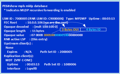
The MP2MP Tree is uniquely identified in the network by looking at the [Root, Opaque Value] pair, the other two entities that give us information about the tree are the Upstream Clients and the Replication (downstream) clients, here upstream is toward the root (PE6 itself is the root, so we have no upstream clients), downstream is toward the leaves of the tree where packets exit the tree, at this step we have only one replication client that is the Virtual Lspvif0 that terminates the tree on this router, all packets exiting the tree will be delivered to this interface and then to the vrf attached to it, Lspvif0 is then the point where the branch of the multicast tree of the customer joins the MP2MP tree of the Service Provider.
Let’ move out from PE6 and let’s jump on P3 the first P routers attached to PE6, first thing to note is that PE6 and P3 are mldp neighbors:
PE6#show mpls mldp neighbors
MLDP peer ID : 10.0.0.203:0, uptime 01:08:22 Up,
Target Adj : No
Session hndl : 1
Upstream count : 0
Branch count : 0
Path count : 1
Path(s) : 10.0.0.29 LDP FastEthernet0/1
Nhop count : 0
Beside that, looking at debug messages and mldp info on all other P and PE routers I have no mldp activity in the network, I registered no mldp logs and for example if look at P3 I see:
P3#show mpls mldp neighbors | i peer
MLDP peer ID : 10.0.0.106:0, uptime 01:15:50 Up,
MLDP peer ID : 10.0.0.104:0, uptime 01:15:50 Up,
MLDP peer ID : 10.0.0.202:0, uptime 01:15:12 Up,
MLDP peer ID : 10.0.0.201:0, uptime 01:15:12 Up,
P3#show mpls mldp database
* Indicates MLDP recursive forwarding is enabled
As expected P3 has 4 MLDP neighbors but has not created any MLDP structure yet, though I added a MLDP Root to the network, this could seem strange, but it is something that must be expected too, because all the process of building a multipoint tree is left to the leaves of the tree and not to its root. Let’s then add a leaf to the game, starting from PE1:
PE1(config)#ip vrf C-ONE
PE1(config-vrf)#mdt default mpls mldp 10.0.0.106
Dec 11 2017 12:47:44.607 ITALY: MLDP: LDP root 10.0.0.106 added
Adding the root of the tree on a leaf via configuration starts some mldp activity on the network, below you can find a picture with the relevant messages generated by each node:
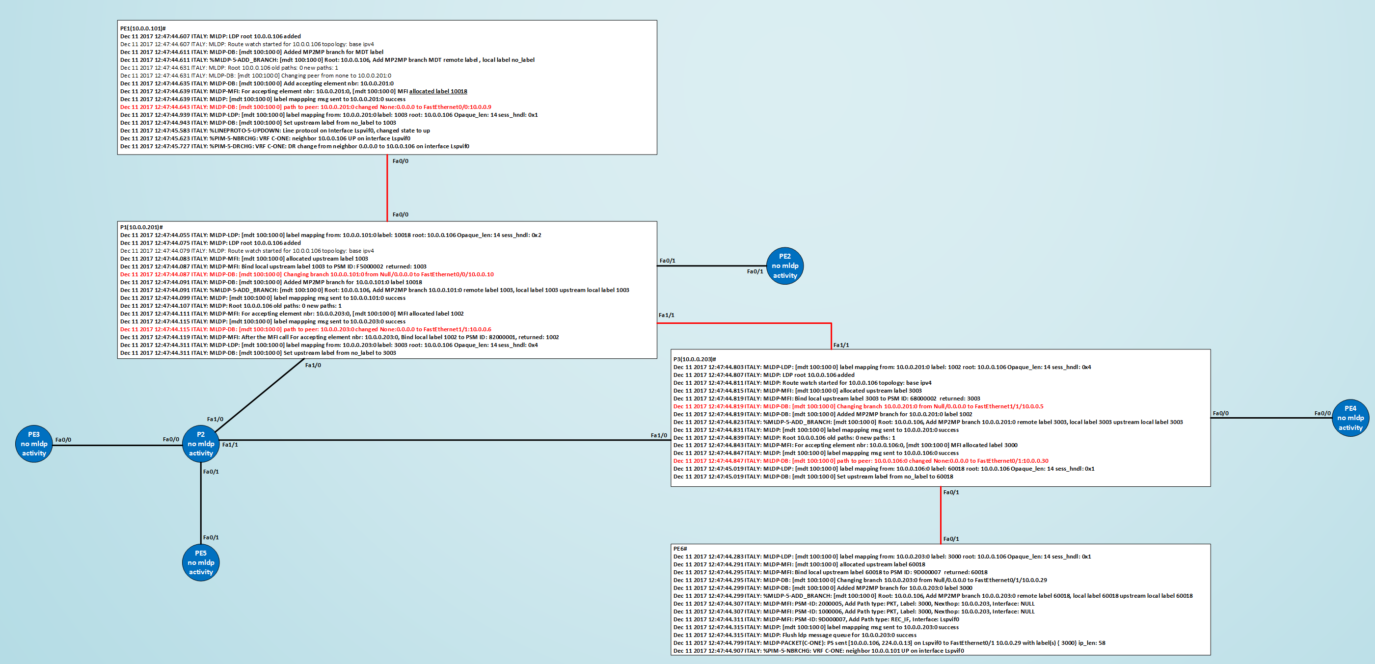
Looking at the messages and at the built mldp database is possible to see some important things:
1] The signaling of the tree is initiated by the leaf (in this case PE1).
2] When a leaf is activated configuring the root address, it sends label mapping messages containing the association between the FEC representing the Tree (Root Address, Opaque Value) and an mpls label allocated by the node, this info is sent to the the next-hop selected for the root ip address (downstream binding).
3] When the next node, toward the root, receives this binding it adds branches to the tree (the red lines in the figure) and replies to the previous node, with another binding, an upstream binding, sending a similar label mapping message to it, each node sets two groups, one group made of Replication Clients (where to replicate and send multicast packets received on the tree) and Upstream Clients (more on this later on).
4] It’s this exchange of Label Mapping Associations that builds the tree.
5] PE1 and PE6 become PIM Neighbors on interface Lspvif0
Below you can see two of these Label Mapping Messages exchanged between PE1 and P1:
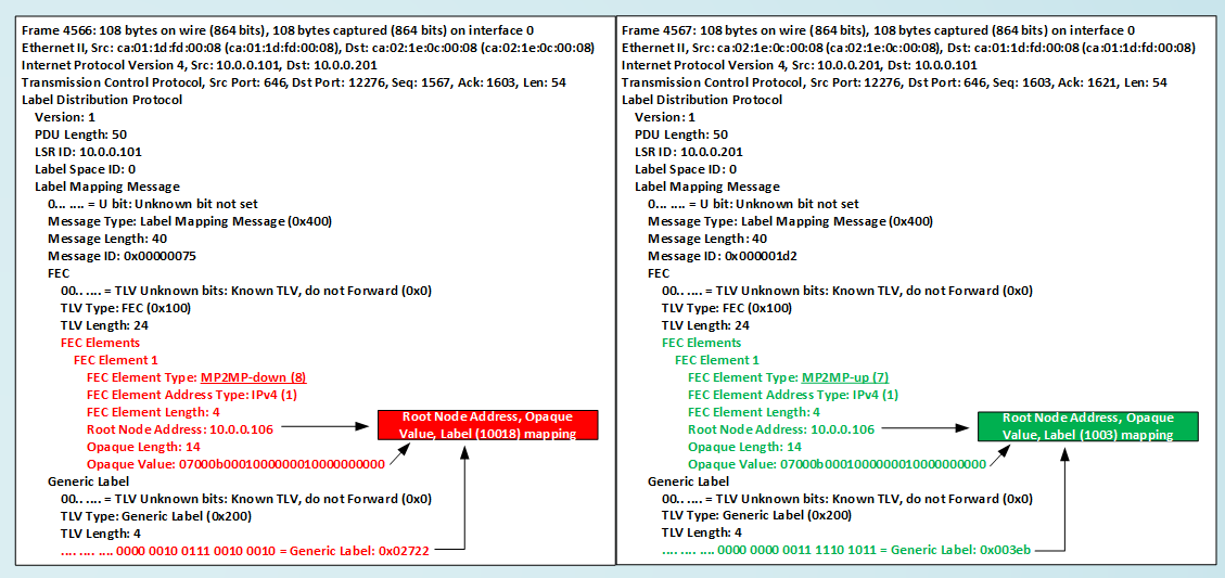
Things to remember are the two types of FEC element MP2MP-down and MP2MP-up that are essentially coded in the same way, both contain elements to identify the tree (Root Address, Opaque Value) and the mapping between these FECs and the labels.
NOTE: at the time I was wrting this part of the post, I was using a Wireshark version on Ubuntu that could not understand MP2MP FEC elements, this was due to a WS bug 13171, only after recompiling Wireshark from its source code with the fix for that bug I was able to see MP2MP FEC elements decoded in the right way.
This exchange of label mapping messages floods down to the root and at each node downstream/upstream labels are assigned to the tree, when the process is completed the mldp database and the tree can be seen as shown here:
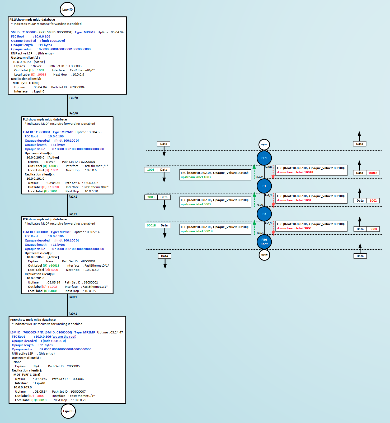
Figure shows the mldp database installed in each node and the labels installed in upstream and downstream direction, the bidirectional nature of the tree should be evident, despite of that, when the root receives a multicast packet it must put it on the P2MP way of the tree in the downstream direction (from itself to the leaves) in such a way that all the active leaves can receive it, when a leaf wants to send data on the tree it must put it on the MP2P (a.k.a P2P) way of the tree in the upstream direction toward the root, the transit nodes, generally speaking P-routers (but more precisely every router that has reachability of the root via an upstream neighbor and one or more downstream neighbors), must send the data in the upstream direction toward the root and in the downstream direction toward other possible leaves reachable through itself. Now, when approached for the first time all these upstream/downstream directions/labels stuff could be confusing. To really appreciate the MP2MP nature of the tree it’s better to have more than one branch and having some nodes operating as a merging point. Let’s move to see what this mean, I activate PE3 as a new leaf.
NOTE: To write this long post at some point I was forced to shut down my workstation, otherwise my wife could have put me out in the street, so it’s possible that from one section/test to another, you see different labels in the different pictures, I hope you can however grasp the concept, the next test falls under one of this period of workstation off/on, so the labels used so far will not be present any more and replaced by others, I will try to be detailed as much as possible.
PE3(config)#ip vrf C-ONE
PE3(config-vrf)#mdt default mpls mldp 10.0.0.106
Let’s see in the following figure how are populated the mldp database on relevant nodes and a visual representation of this MP2MP Tree made of its P2MP (from Root to Leaves) and MP2P (a.k.a P2P) parts.
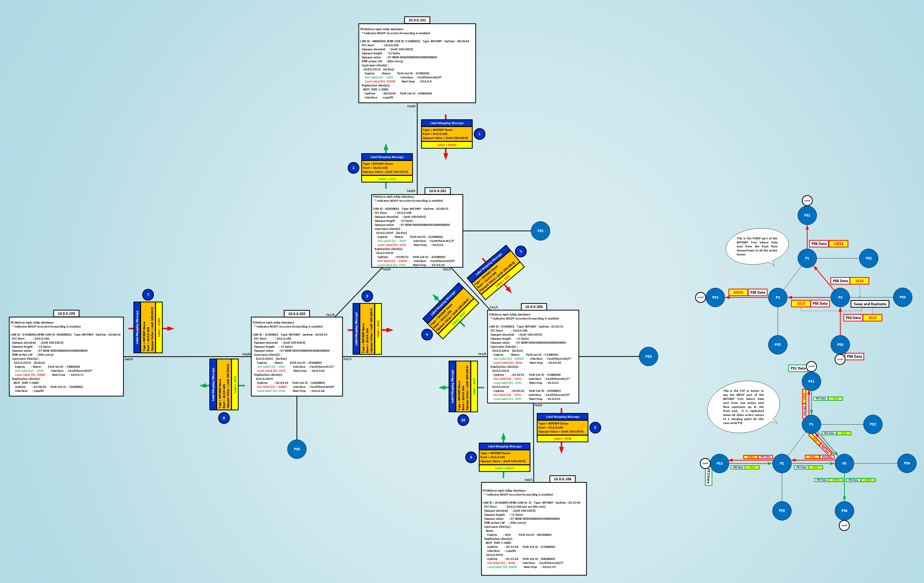
The figure should summarize some important aspects.
In its left side I wrote for each node how they built their mldp database, you can see for each node replication clients and upstream clients, you can see also the exchanged label mapping messages between routers and the respective labels in upstream and downstream directions, also I used numbered blue circles to give you an idea of which is the sequence of steps that the network follows in building the MP2MP Tree, you must read them supposing that you first activate Leaf PE1, wait for PE1 and PE6 becoming PIM neighbors on their LSPVIF0 interfaces, and then activate Leaf PE3, of course if you follow another sequence of leaves activation some states on the tree can be built before than others with respect to my example, but the final status of the tree will be the same from a forwarding point of view (except that you could find different labels). This side of the figure should alert you about the fact that every time a node receives a downstream MP2MP FEC-to-Label Mapping message, it replies to this message sending an upstream MP2MP FEC-to-Label Mapping one, it does this thing for every downstream MP2MP FEC received, after that it allocates downstream labels for the same FEC that identifies the tree and floods its downstream MP2MP message to the valid next-hop through which it can reach the Root of the Tree.
In the right side of the figure, you can see the two parts that form this MP2MP Tree from a data plane point of view, the P2MP part originating in the root and reaching all the active leaves (the red arrow lines in the upper right side) and the MP2P part that originates in all active leaves and reach the root (the green arrow lines in the bottom right side).
I reported for both parts which are the labels used, let’s try to check on the routers the mpls forwarding states. Let’s start from the P2MP part.
MPLS FORWARDING STATES ON P2MP TREE (from the root to all the active leaves)
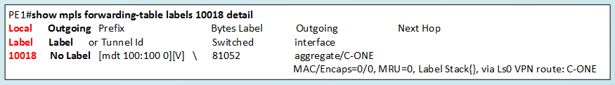
Let’s suppose that PE6 receives a multicast packet on its vrf interface, which are the labels it must use to switch the packet in the network? For sure based on the topology PE6 must send this packet to P3, we can say that it must replicate this packet for P3, in the figure you can see that for this tree, the received downstream label from Replication Client P3 (10.0.0.203) is the label 3016, this label must be pushed on the packet and the labeled packet sent to P3, this command can be used to verify this:
PE6#show mpls mldp database | i Out
Out label (D) : 3016 Interface : FastEthernet0/1*
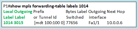
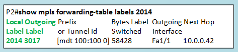
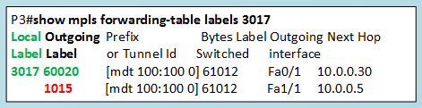
Let’s move on the interesting node, P3, when P3 receives a labeled packet with label 3016 what it does?
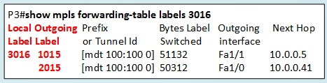
Note that the command is the same used for normal ldp, it tells me that P3 on receiving a packet with label 3016 must do these operations, 1) remove label 3016 from the packet, buffer the original packet somewhere and 1) push label 1015 on the original packet and send it out of its fa1/1 interface toward P1, 2) push label 2015 on the original packet and send it out of its fa1/0 interface toward P2, you can consider this operation like a swap & replicate operation.
When the labeled packet moves on the branch of the tree at each node if more than one replication client is present, similar swap&replicate operation must be done. In this example, P1 and P2 has only one replication client their respective PE (because only leaves PE1 and PE3 are configured for mdt), the operation that must do P1 and P2 can be seen here:
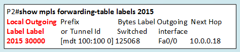
When the packets reach PE1 and PE3 we don’t need labels any more:
The packets are delivered to the VRFs.
MPLS FORWARDING STATES ON MP2P TREE (from a leaf to the root and to other leaves):
Suppose now that is PE1 that wants transmit some multicast info to other nodes on the tree, what it can do is sending its data upstream to the root hoping that the root or some other entities forward the data for all the interested node:
PE1#show mpls mldp database | i Out
Out Label (U) : 1014 Interface : FastEthernet0/0*
PE1 sends the packet to P1 pushing label 1014 (the upstream label received by its upstream client).
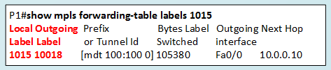
When the packet reaches P1, what does this router do?
It simply swaps the label 1014 with the label 3015, why 3015? Because is the upstream label received by its upstream client P3, let’s move on P3 where again some “magic” happens:
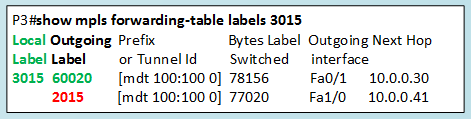
P3 does again a double swap&replicate operation, let’s pay attention at the labels used to swap label 3015, toward PE6 that is an upstream client it uses label 60020 that is the upstream label sent by PE6 to P3, toward P2 it uses label 2015 that is the downstream label advertised by P2 to P3 to reach Leaf PE3 in the downstream direction, P3 then swap an upstream label with a downstream label, note hence that this is the same label used on the P2MP Tree where traffic flows from the root to the leaves. In other words, P3 is a merging point where traffic flows on both type of trees (of course this is only a way to see this thing, what really matters are the labels and the forwarding states in each node). If you follow the green arrowed lines you can simply recognize the nature of the MP2P Tree, any leaves can talk multicast to the root following the upstream label binding, what must be added here is that to have Leaf to Leaf communication, at some point in the network a merging node must replicate the packet that comes from a leaf to other leaf that are downstream clients. A similar thing happens for the data sent from PE3:
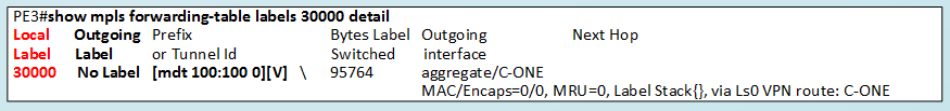
PE3#show mpls mldp database | i Out
Out Label (U) : 2014 Interface : FastEthernet0/0*
You can see again how data received on P3 on its fa1/0 interface is replicated to PE6 using upstream label 60020 and to P1 using downstream label 1015.
Now, coming back to the beginning of this post it should be clear that Label switching packets on the upstream part of a MP2MP mLDP Tree is completely different than Label switching unicast packets, for example here I drew the unicast LDP Tree to reach 10.0.0.106 (PE6’s Lo0) from PE1 and PE3, and I compared it with the data plane built in the case of mLDP when sending data in the upstream direction (from Leaves to the Root):
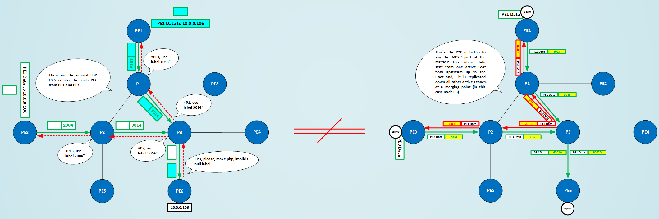
If I must find some similarities between the two trees, the only one that I can find is that in both cases starting from the node I must reach (PE6, the root) some sort of label signaling flows from PE6 up to the leaves PE1 and PE3, then each node uses these labels to send the data, and that the physical paths used by real data are the same (the green arrowed lines) but even the terminology we use is different, in the case of tree on the left side (Unicast LDP), the signaling is downstream unsolicited, that is, the node X where the prefix is reachable, allocates a label and floods it to all its LDP neighbors, then only the upstream neighbors (the nodes that have X as downstream next-hop to this prefix) will install it in the mpls forwarding table. In the case of the mLDP tree (at the right) we say that the signaling is upstream and is in some way solicited because every node generates an upstream label only when a downstream label mapping message is received, furthermore the labels used for mLDP are completely different, and, last but not least, in mLDP nodes must not use implicit-null-label for PHP, so pay attention when comparing the two cases if you want to do it.
Now, I should have enough elements to complete the big picture, remember that I only activated two leaves PE1 and PE3 so far, let’s then activate the other PEs and see how the real data plane is, capturing some packets on the wires.
When all PEs are active and configured for MDT/mLDP they must become PIM neighbors on their Lspifv0 interfaces (note that here I have only one tree, if you have more than one the id of the virtual LSP interface could be different). Let’s check this.
NOTE: Labels you see here are different from the ones you’ve seen so far because I restarted all simulation environment (see previous NOTE if you are curious about the reason).
Next figure shows that all PEs become PIM neighbors as expected, and gives details about the built mLDP databases:
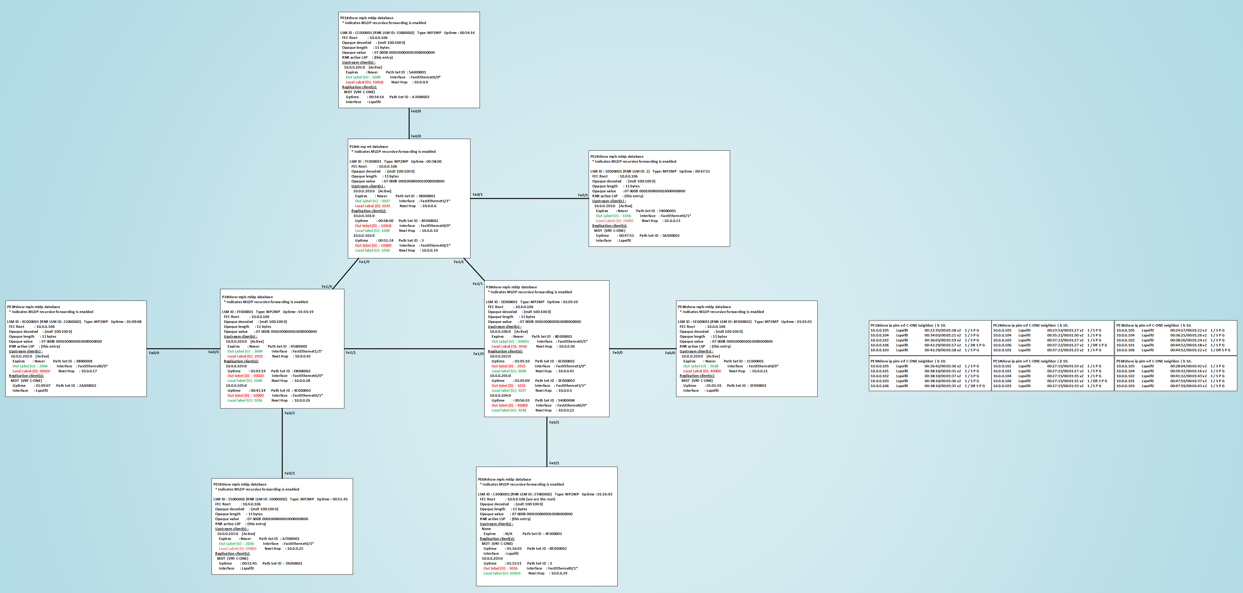
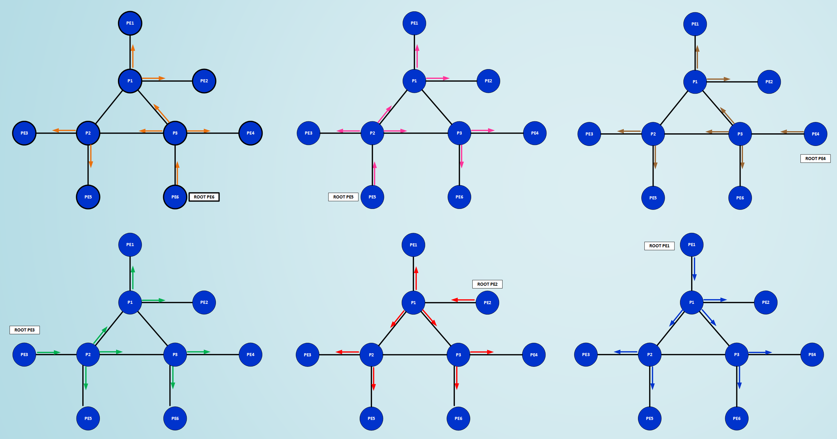
Green Labels are Upstream ones, Red Labels are Downstream ones, we can see that P3 is the node with the largest mLDP database, it is the crossroad of the network and it is the node that must support the most of the replication job done on the network, this is due to the topology and to the fact that I chooses PE6 as the root of the MP2MP Tree, Root node can be considered like a traffic attractor when it receives multicast traffic and like a flooder of multicast traffic when it sends multicast data, these things should be more evident looking at the next figure.
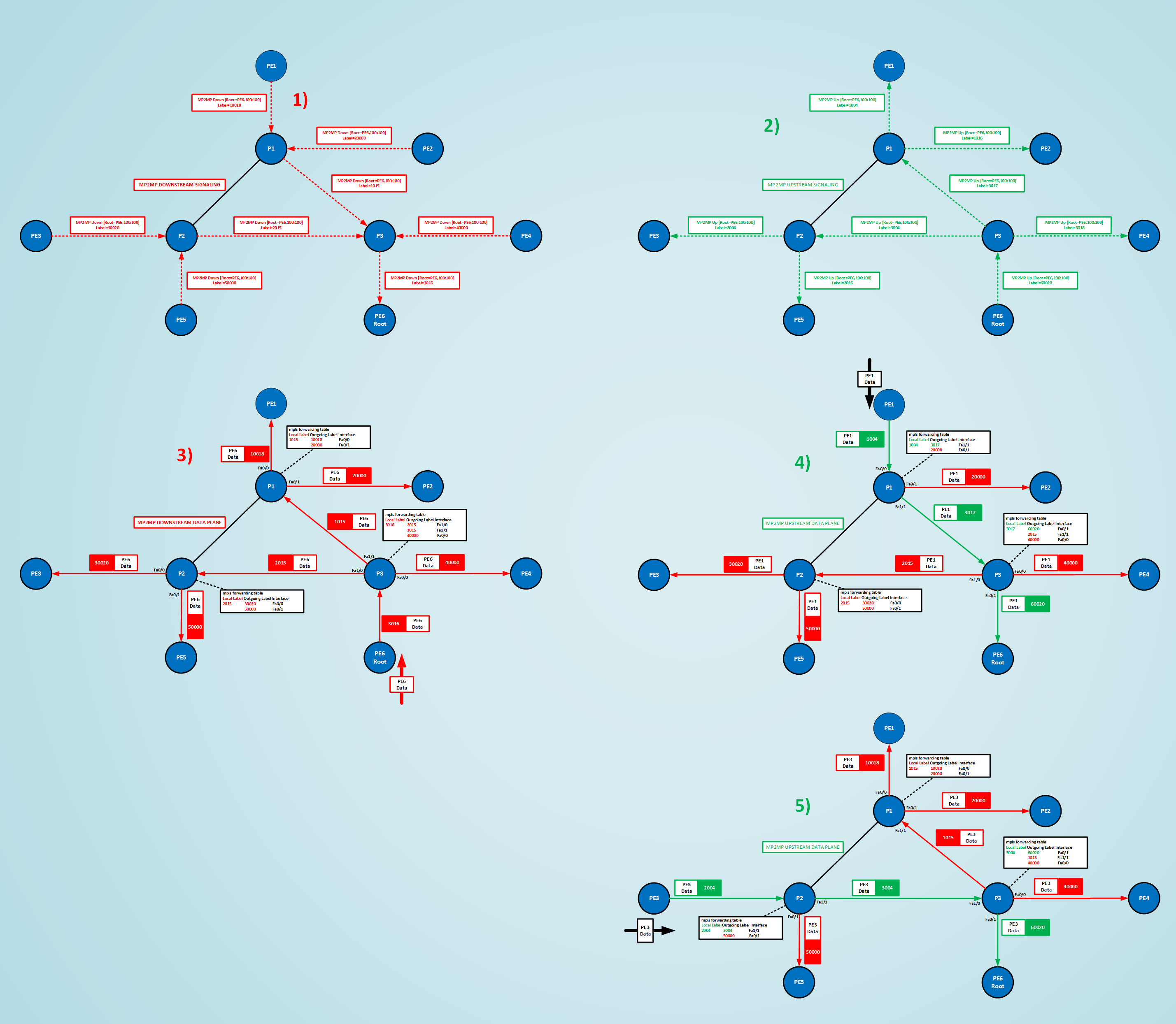
Here I drew five trees, tree 1) and 2) show control plane signaling, on tree 1) you can see downstream label signaling initiated by each leaf, each node receiving a downstream label mapping message propagate a self-generated label mapping message to the next-hop toward the root; on tree 2) you can see upstream label signaling, this labels are sent at each node in response to the received downstream label mapping message. Trees 3), 4) and 5) show data plane forwarding in three different cases, when PE6, the root, sends data on the P2MP Tree, when PE1 as Leaf sends data on the MP2P tree, when PE3 as Leaf sends data on the MP2P Tree respectively. I also reported the interesting mpls forwarding tables so it should be easy to look at how nodes swap labels, in the latter two cases [Trees 4) and 5)] you can see that when a Leaf sends data toward the Root its data follow the shortest upstream path toward the root (the green arrowed one), again, with this meaning you can see the transmission of data from the leaf to the root on the upstream tree as a P2P LSP, but you can see also that at some merging node data sent by leafs on the upstream tree are downstream replicated toward other leaves, this is done for example on all three P routers (P1, P2 and P3) depending on which Leaf is sending data.
Now, the MPLS core seems ready to support multicast traffic of the customer, I verified the PIM neighborship between all PEs (like happens for MDT/PIM) and the MPLS forwarding states on each node, the final step is then activating CEs, RP, Source and Receivers and check if the multicast solution of the customer behind VRF C-ONE works through the Service Provider Core. Here I will do exactly what I’ve done in the first part of the post when I used MDT/PIM to tunnel C-Multicast traffic, I summarize here what I configured for the customer behind this VRF:
- Customer will use its own Rendezvous Point C-RP connected behind CE5, RP’s IP Address is 172.16.5.6
- Customer will use Bootstrap Router Method to distribute RP info among its sites, the same router C-RP will act as RP and Bootstrap Router
- Customer has a source of multicast traffic behind CE6, source is sending multicast data with source IP 172.16.6.6 to this group 226.0.0.6 (I configured an IP sla sending icmp echo to group 226.0.0.6 to simulate a source)
- Customer has two receivers C-Rcv3 and C-Rcv2 behind CE3 and CE2 respectively
If everything works fine I should see that all involved CEs should know about the RP and installed multicast entries in their mribs of the type (*, 226.0.0.6) and (172.16.6.6, 226.0.0.6), active forwarding should be on the SPT toward the source. The final test will be simply sending a ping from the source to the group 226.0.06, both receivers must respond. Here you can open the topology for reference.
NOTE: As I described in the first part of the post, you MUST support L3 MPLS/VPN unicast exchange of RP’s and source’s IP prefix, to have a fully working Multicast solution for the customer, look at the first part of the post to understand why, to exchange BGP VPNv4 routes I used the router called Provider-RP as BGP Route-Reflector, I didn’t change the host name, but don’t be confused, when using mLDP you don’t need a PIM/RP in the core, so despite its name, in this test the router it’s only a BGP Route Reflector
Here the ping tests confirming multicast solution works fine:
C-Source#ping 226.0.0.6 source 172.16.6.6
Type escape sequence to abort.
Sending 1, 100-byte ICMP Echos to 226.0.0.6, timeout is 2 seconds:
Packet sent with a source address of 172.16.6.6
Reply to request 0 from 172.16.2.6, 70 ms -> C-Rcv2
Reply to request 0 from 172.16.3.6, 80 ms -> C-Rcv3
C-Rcv-3#ping 226.0.0.6 source 172.16.3.6
Type escape sequence to abort.
Sending 1, 100-byte ICMP Echos to 226.0.0.6, timeout is 2 seconds:
Packet sent with a source address of 172.16.3.6
Reply to request 0 from 172.16.3.6, 5 ms -> of course receivers reply to themselves
Reply to request 0 from 172.16.2.6, 110 ms -> C-Rcv2
C-Rcv-2#ping 226.0.0.6 source 172.16.2.6
Type escape sequence to abort.
Sending 1, 100-byte ICMP Echos to 226.0.0.6, timeout is 2 seconds:
Packet sent with a source address of 172.16.2.6
Reply to request 0 from 172.16.2.6, 4 ms -> of course receivers reply to themselves
Reply to request 0 from 172.16.3.6, 107 ms -> C-Rcv3
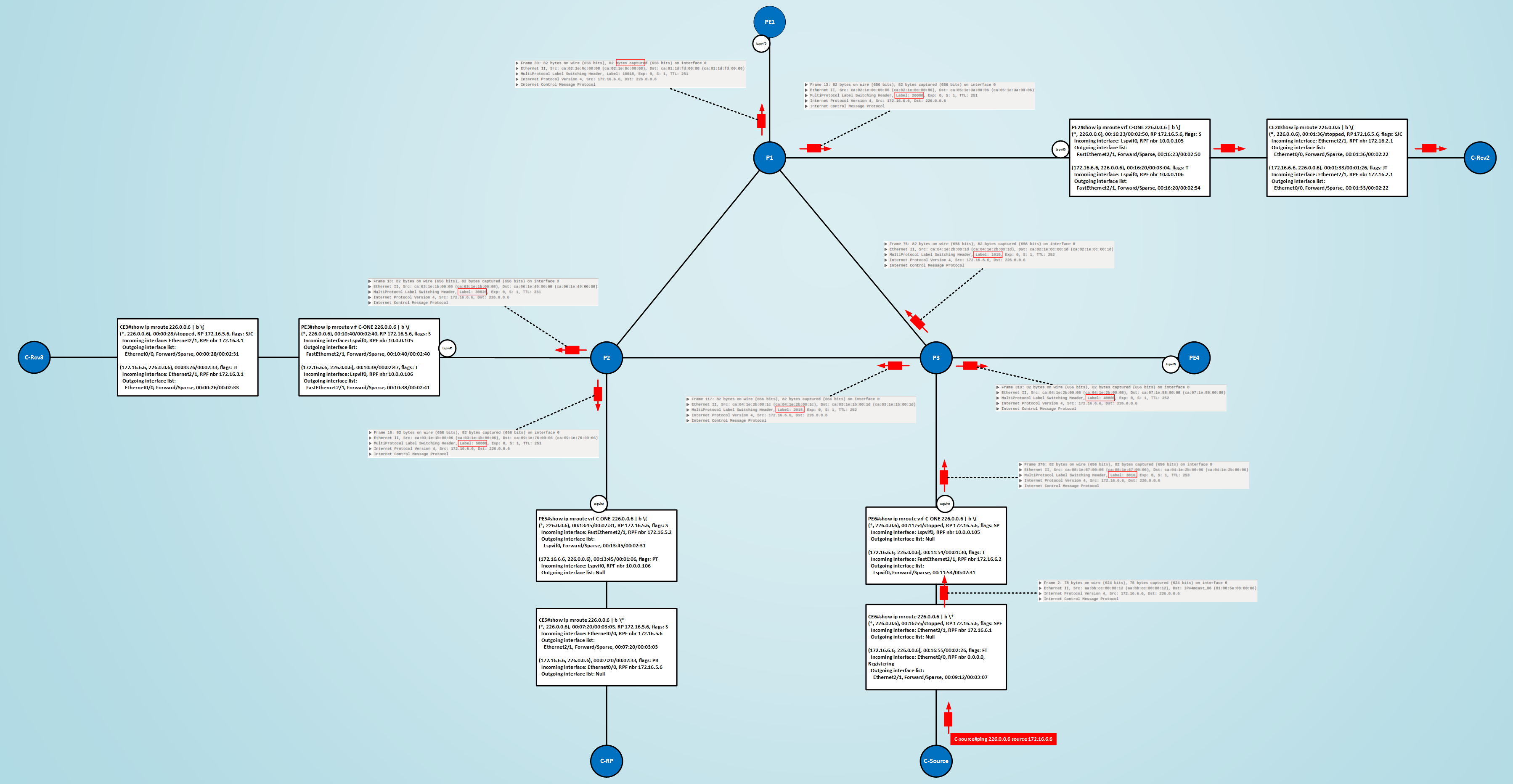
Below you can find a final figure where I reported the relevant multicast entries for the VRF Customer on PEs and CEs, and the captured ping packets from the source that show how multicast packets are Labeled Switched inside the core, you can see on the real packets the labels I drew on previous picture:
NOTE: In this post I didn’t mention DATA MDT, you can review what an MDT Data is in this other post, the logic to create a DATA MDT using mLDP is the same of the MDT Default case, as for PIM/mGRE the MDT Data structure is used when a traffic threshold is crossed on the default mdt tree, just to mention the commands you can create the MDT Data Tree using mLDP adding this two commands under the VRF: mdt data mpls mldp “number of MDT structures” + mdt data threshold “x”
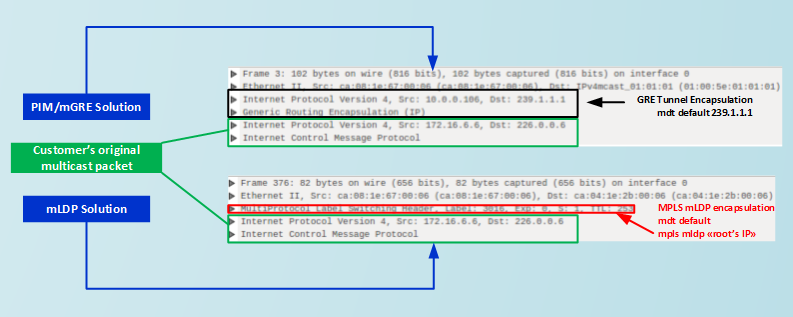
Here you can compare how the same multicast ping from customer’s source is switched inside the core using the two different solutions PIM/mGRE and mLDP
PIM/mGRE Multicast VPN (Profile 0)
PIM is used inside the core.
- You need a Rendezvous Point inside the core if MDT Default groups are used in Sparse-Mode.
- mGRE Tunnels providing encapsulation for C-multicast traffic are instantiated by the presence of BGP MDT Address-Family (at least with IOS used for my test (c7200-adventerprisek9-mz.122-33.SRE15) on PEs, active BGP sessions are not needed in this case, PEs discover each other through the Rendezvous Point in the core.
- If MDT Default Groups are working as SSM Groups you MUST enable iBGP relationships between PEs under MDT address family, in this way PEs can discover each other using BGP MDT Extensions.
- On MDT Default Groups unnecessary multicast traffic is replicated to PEs that has not interested receivers behind them, to overcome this use MDT Data groups.
- You MUST enable L3 MPLS/VPN to exchange C-unicast routing info to let routers pass RPF check for multicast behind the vrf.
- Transport of C-multicast packets is pure IP/mGRE encapsulation (no MPLS labels are used though you have LDP in the core to support L3 MPLS/VPN)
mLDP MP2MP LSPs (Profile 1)
- No PIM needed in the Core, then no Rendezvous Point in the core is needed
- Lspvif logical interfaces are instantiated configuring the root IP address on PEs
- No special Address Family under BGP is needed
- On MDT Default Groups unnecessary multicast traffic is replicated to PEs that has not interested receivers behind them, to overcome this use MDT Data groups.
- You MUST enable L3 MPLS/VPN to exchange C-unicast routing info to let routers pass RPF check for multicast traffic behind the vrf.
- Transport of C-multicast packets is Label Switched, Labels used are allocated from a process starting on the Leaves of the Tree (Downstream Signaling), for every downstream label mapping message a node reply with an Upstream Label Mapping Message (Upstream Signaling). Traffic flowing from the Root of the Tree down to the leaves will be switched using Downstream Labels, traffic from the Leaves to the Root will be switched using upstream labels, at some merging point the nodes that receive traffic in upstream direction will replicate this traffic in downstream direction (if they have active branches downstream), using downstream labels to replicate traffic toward other Leaves.
I wrote many words ago about the positioning of the root, I’m not an mVPN designer expert, but I can say that generally speaking, the Root attracts the most of the signaling and based on the topology the nodes immediately next to it could find themselves in doing most of the replication job (P3 in my test), here for example I selected PE6 as Root because I had a source of the customer behind it; another factor to consider is that when you use mdt data groups, PEs will announce themselves as root of the new data trees, then, again, generally speaking, you should consider that PEs and replication routers in the P network should be powerful enough to handle all this stuff, not a great design hint I know, but I have no time to do further tests.
Many other profiles exist beyond Profile 0 and 1, in the next future If I have time, I will do some test on different profiles, interesting ones could be for example profiles that use P2MP-Traffic Engineering LSPs.