Section 2 – L2TPv3 Pseduowires
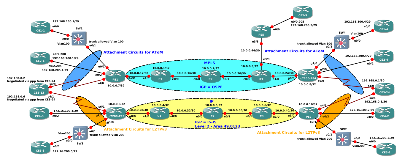
In Section 1 I made some tests about AToM Ethernet Pseudowire reviewing some basic concepts, here I will continue in Pseudowire world giving a look at L2TPv3 pseudowires. AToM and L2TPv3 have, practically speaking, the same target, that is extending Layer 2 service over a Layer 3 one; in case of AToM you will use an MPLS backbone and in case of L2TPv3 you will use a pure IP Backbone (no mpls; in case you want to give a look at one possible scenario where you can meet a pure IP transport you can read this other article I wrote about using L2TPv3). I will use is the same network topology I used for AToM case but using only the IP enabled backbone (C1-C2-C3 routers), see below the topology
Main differences between ETHoMPLS and L2TPV3 will be the used encapsulation and the signaling methods that I recap here (see Section 1 for more details)
ETHoMPLS: original frame (tagged or untagged, the tag will be preserved or stripped off based on which type of pseudowire you are using 0x0004/0x0005 and on how you configure the PEs) is encapsulated under a TWO LEVEL MPLS LABEL STACK and under an optional Control Word. The frame that results from this operation, let’s say an ETHoMPLS packet is then transported from the Ingress PE to the Egress PE. ETHoMPLS pseudowire is made of a 2 MPLS unidirectional Label Switched Paths (LSPs). Pseudowire is then out of band signaled using Label Distribution Protocol (LDP), in other words LDP distributes the the TWO LEVEL MPLS LABEL STACK, that simply means distributing the two labels, the outer label (tunnel label or igp label other usable names) that switches the packet between the the loopbacks of ingress and egress PE in the mpls core, and the inner label (other names VC Label or Pseudowire Label) that identifies the pseudowire established bewteen the 2 PEs. Outer Label is distributed link-by-link as per normal LDP operation between PEs and P routers in the core, inner label is distributed with Targeted LDP sessions between the ingress and the egress PEs.
L2TPv3: original frame (tagged or untagged, the tag will be preserved or stripped off based on which type of pseudowire you are using 0x0004/0x0005 and on how you configure the PEs) is encapsulated under an IP header that will identify an IP Tunnel between the ingress and egress PEs. In this case the L2TPv3 pseudowire is inherently bidirectional, and you can have an automatic and optional in band signaling, in other words is the L2TPv3 protocol itself that could establish a Control Channel between ingress and egress PEs and different pseudowires are signaled using this already established control channel.
Now, before making a test to see how L2TPv3 works it’s better to introduce first some terminology that when traduced in IOS terms can be some way foggy:
Control Channel is named L2TPv3 TUNNEL in IOS terms. A L2TPv3 TUNNEL is identified by a (LocTunID,RemTunID) pair, this pair is exchanged by ingress and egress PEs using a 3-way handshake mechanism, main exchanged messages are Start Control Connection Request (SCCRQ), Start Control Connection Reply (SCCRP), Start Control Connection Connected (SCCCN)
An L2TPv3 Pseudowire is named SESSION in IOS terms. A L2TPv3 SESSION is identified by a (LocID,RemID) pair, this pair is exchanged using the already established TUNNEL, main exchanged messages are Incoming Call Request (ICRQ), Incoming Call Reply (ICRP), Incoming Call Connection (ICCN)
As first example let’s build an Ethernet L2TPv3 Pseudowire for transporting frame between CE routers CE5-3 and CE5-2. CEs are simply configured with an IP address that belongs to VLAN200 configured on the local switch where they are connected via e0/0 interface
CE5-3#show run int e0/0 | b interface
interface Ethernet0/0
ip address 172.16.200.5 255.255.255.248
CE5-2#show run int e0/0 | b interface
interface Ethernet0/0
ip address 172.16.200.2 255.255.255.248
Like the case of AToM, Pseudowires will be configured on PEs routers in this case this devices are c7200-PE3 with Loopback0 10.0.0.9/32 (a virtual 7200 router running 152-4.M10) and PE2 with loopback 10.0.0.10/32 (a generic virtual IOS running 15.4.1T)
First requirement is that IP connectivity between PE is ok:
c7200-PE3#traceroute 10.0.0.10 source 10.0.0.9
Type escape sequence to abort.
Tracing the route to 10.0.0.10
VRF info: (vrf in name/id, vrf out name/id)
1 10.0.0.29 32 msec 28 msec 8 msec
2 10.0.0.34 4 msec 12 msec 12 msec
3 10.0.0.38 12 msec 8 msec 12 msec
4 10.0.0.42 12 msec 8 msec 8 msec
On PEs interfaces that will receive the frames from the switch are two dot1q subinterfaces:
c7200-PE3#sh run int g1/0.200 | b interface
interface GigabitEthernet1/0.200
encapsulation dot1Q 200
shutdown
PE2#sh run int e0/1.200 | b interface
interface Ethernet0/1.200
encapsulation dot1Q 200
shutdown
Now, from Section 1 I should know everything about how configure PEs in such a way that I can control the type of established Pseudowire and how to preserve and remove the tag from the original ethernet frame, then I will use a pseudowire-class on both PEs to preserve the tag present on original frame and for signaling a 0x0004 PW TYPE.
c7200-PE3#sh run | s pseudo
pseudowire-class PW200
encapsulation l2tpv3
ip local interface Loopback0
PE2#show run | s pseudo
pseudowire-class PW200
encapsulation l2tpv3
interworking vlan
ip local interface Loopback0
The pseudowire-class specifies the type of encapsulation (L2TPv3) and the IP interface that PE must use to form the IP Header for encapsulating the original frame under the tunnel. For PE2 I specified also the type of interworking (vlan) that causes PE2 to use PW TYPE 0x0004, for the 7200 router this is instead the default type of interworking.
The last piece of missing info is the xconnect command under the Attachment Circuits (interface toward the switches), notice how ACs are still in shutdown. Before configuring the xconnect commands I will activate packet captures on the PE interfaces looking at the IP core. Pseudowire configuration is here:
c7200-PE3#sh run int g1/0.200 | b interface
interface GigabitEthernet1/0.200
encapsulation dot1Q 200
shutdown
xconnect 10.0.0.10 200 pw-class PW200
On remote PE2 I have not configured any pseudowire info (no xconnect command), as soon as I configured xconnect command on c7200-PE3 this PE has enough info to start to establish the Control Session (a.k.a Tunnel) with the remote peer PE2. Below a figure with the 3-way-handshake mechanism that PEs must complete to establish the Control Channel:
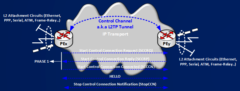
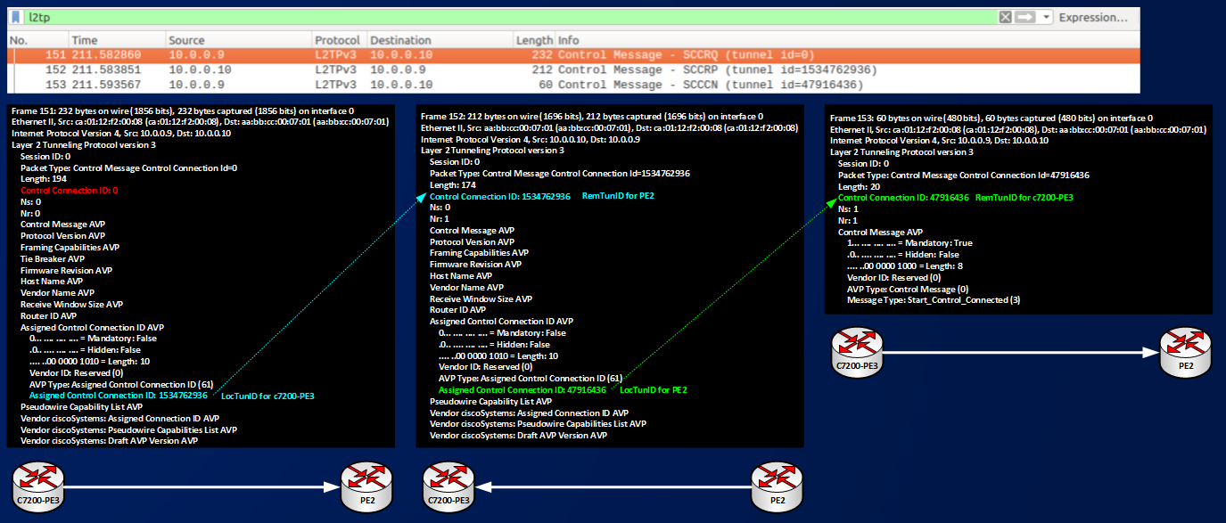
Here you can see the sequence of L2TPv3 messages that are exchanged in this phase:
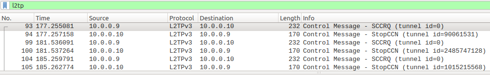
Simply speaking, c7200-PE3 contact PE2 with an SCCRQ message, PE2 is not configured for answering (no xconnect command), PE2 stops c7200-PE3’s attempt with a Stop Connection (StopCCN) message. The cycle repeats. We can see that routers assign a Local Control Connection ID to their control channel and that they advertise this IDs to the peer. Figure shows how every time c7200-PE3 receives a StopCCN it renew its local assigned control connection IDs (90061531, 2485747128, 1015215568), below you can find a SCCRQ packet expanded in some relevant fields:
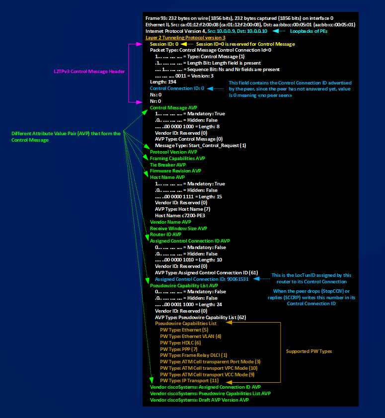
Looking at the figure you can see that an SCCRQ message is made of a Header and some Attribute Value Pairs that specifies some capabilities of the router sending the message. To identify the Control Session (L2TPv3 Tunnel in IOS terms) routers use Control Connection IDs, the ID used in the header of the message tells for which of the Local Connection of the peer the message is used for, in this case the SCCRQ message is the first message sent by c7200-PE3 to PE2 then c7200-PE3 cannot know which is the Remote-ID of the peer and sets 0 in Control Connection ID. At the same time it advertise its LocTunID to the peer writing it in the AVP named Assigned Control Connection ID. Let’s continue with configuring PE2 too and let’s see how the Control Session establishment ends.
PE2#sh run | s pseudo
pseudowire-class PW200
encapsulation l2tpv3
interworking vlan
ip local interface Loopback0
PE2#sh run int e0/1.200 | b interface
interface Ethernet0/1.200
encapsulation dot1Q 200
shutdown
xconnect 10.0.0.9 200 encapsulation l2tpv3 pw-class PW200
After this configuration PE2 starts to reply to c7200-PE3, after some time we can see the 3-way-handshake concluded exchanging SCCRQ,SCCRP,SCCN messages:
The figure shows the 3-way-handshake packets and how Control Connection IDs are used, at the end of the process we can check the presence of a Control Session between PEs using these commands:
c7200-PE3#show l2tun tunnel
L2TP Tunnel Information Total tunnels 1 sessions 1
LocTunID RemTunID Remote Name State Remote Address Sessn L2TP Class/
Count VPDN Group
1534762936 47916436 PE2 est 10.0.0.10 1 l2tp_default_cl
PE2#show l2tun tunnel
L2TP Tunnel Information Total tunnels 1 sessions 1
LocTunID RemTunID Remote Name State Remote Address Sessn L2TP Class/
Count VPDN Group
47916436 1534762936 c7200-PE3 est 10.0.0.9 1 l2tp_default_cl
Outputs tell us that PEs found an agreement about how to identify the Control Session, they do that using the pair of IDs (LocTunID,RemTunID)=(1534762936, 47916436) with role inverted between local and remote based on which PE you are looking at.
Now, what this Control Session is used for? The Control Sessions is used to establish and maintain the Pseudowires. I can see the presence of a counter named Sessn Count that in this example counts 1. Here we must not be confused by the terminology:
Control Sessions <==> Tunnels
Pseudowires <==> Sessions
At the moment I have one Control Session (Tunnel) active and one Session (Pseudowire 200) configured. How can I verify the status of the pseudowire? using these commands:
c7200-PE3#show l2tun session
L2TP Session Information Total tunnels 1 sessions 1
LocID RemID TunID Username, Intf/ State Last Chg Uniq ID
Vcid, Circuit
2862077093 0 1534762936 200, Gi1/0.200:200 wtaci 01:09:16 1
PE2#show l2tun session
L2TP Session Information Total tunnels 1 sessions 1
LocID RemID TunID Username, Intf/ State Last Chg Uniq ID
Vcid, Circuit
1390422018 0 47916436 200, Et0/1.200:200 wtaci 01:09:47 0
Here I can see that both PEs have assigned another ID (LocID) to the Pseudowire 200 (Vcid 200) and the LocTunID, here named TunID, that each PE uses to control the pseudowire establishment. Pseudowires are not in up state but in wtaci state meaning that the Local Attachment Circuit is not ready for passing frame, in this case their are in shutdown at both ends. We can notice also that PEs doesn’t see the RemID of the peer assigned by the remote PE, this happens because circuits are in shut then PEs cannot signal the pseudowire.
Next move then is to enable the circuit and see how Pseudowire is established. To establish Pseudowire the process is similar to the one used for establishing Control Sessions, the following picture shows the messages that need to be exchanged to do that:
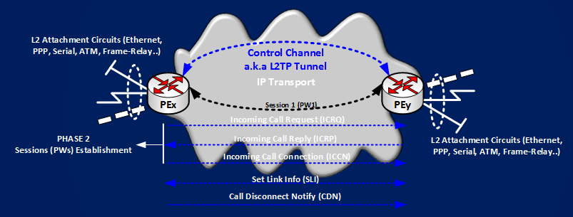
Below you can see the exchanged real packets that build PW 200.
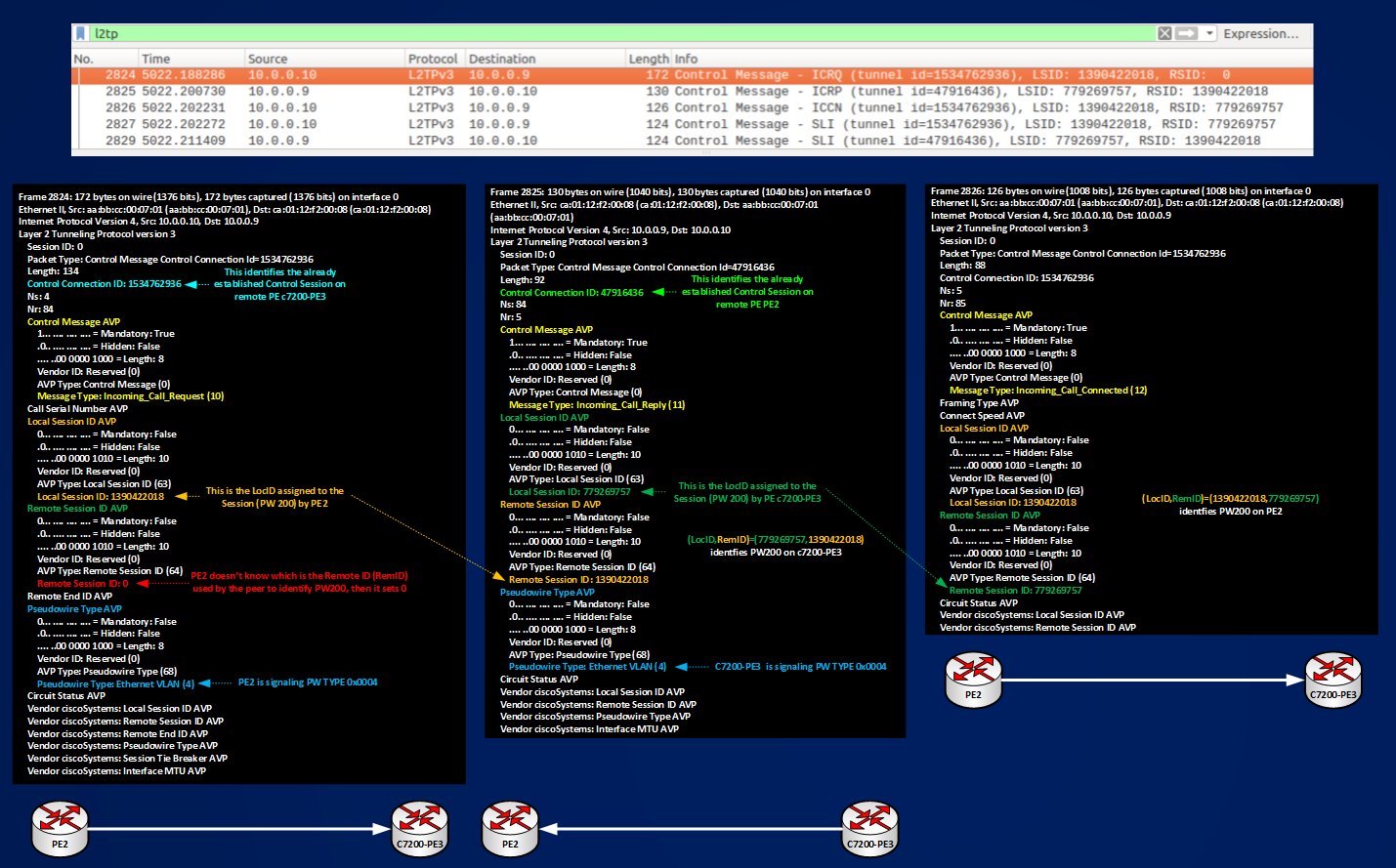
The figure shows how PEs signal PW TYPE 0x0004 based on their configured pseudowire-class or default behavior, that the packets needed to establish PW200 are exchanged over an already established Control Session identified by (LocTunID,RemTunID) pair, and that PW200 is identified by (LocID,RemID) pair, looking at “show l2tun session” it’s possible to verify this IDs:
c7200-PE3#show l2tun session
L2TP Session Information Total tunnels 1 sessions 1
LocID RemID TunID Username, Intf/ State Last Chg Uniq ID
Vcid, Circuit
779269757 1390422018 1534762936 200, Gi1/0.200:200 est 03:01:44 1
PE2#show l2tun session
L2TP Session Information Total tunnels 1 sessions 1
LocID RemID TunID Username, Intf/ State Last Chg Uniq ID
Vcid, Circuit
1390422018 779269757 47916436 200, Et0/1.200:200 est 03:02:49 0
TunID in the above outputs are the LocTunID on each peering PEs.
Now that PW200 is active, last thing to do is sending some data over it to check how data are encapsulated:
CE5-3#show ip arp
Protocol Address Age (min) Hardware Addr Type Interface
Internet 172.16.200.5 – aabb.cc00.0e00 ARPA Ethernet0/0
CE5-3#ping 172.16.200.2
Type escape sequence to abort.
Sending 5, 100-byte ICMP Echos to 172.16.200.2, timeout is 2 seconds:
.!!!!
Success rate is 80 percent (4/5), round-trip min/avg/max = 14/19/23 ms
CE5-3#show ip arp
Protocol Address Age (min) Hardware Addr Type Interface
Internet 172.16.200.2 0 aabb.cc00.1500 ARPA Ethernet0/0
Internet 172.16.200.5 – aabb.cc00.0e00 ARPA Ethernet0/0
CE5-2#show ip arp
Protocol Address Age (min) Hardware Addr Type Interface
Internet 172.16.200.2 – aabb.cc00.1500 ARPA Ethernet0/0
CE5-2#sh ip arp
Protocol Address Age (min) Hardware Addr Type Interface
Internet 172.16.200.2 – aabb.cc00.1500 ARPA Ethernet0/0
Internet 172.16.200.5 0 aabb.cc00.0e00 ARPA Ethernet0/0
Ping and show ip arp tell us that CE5-2 and CE5-3 are transparently interconnected over PW200, let’s see how ping packets are encapsulated:
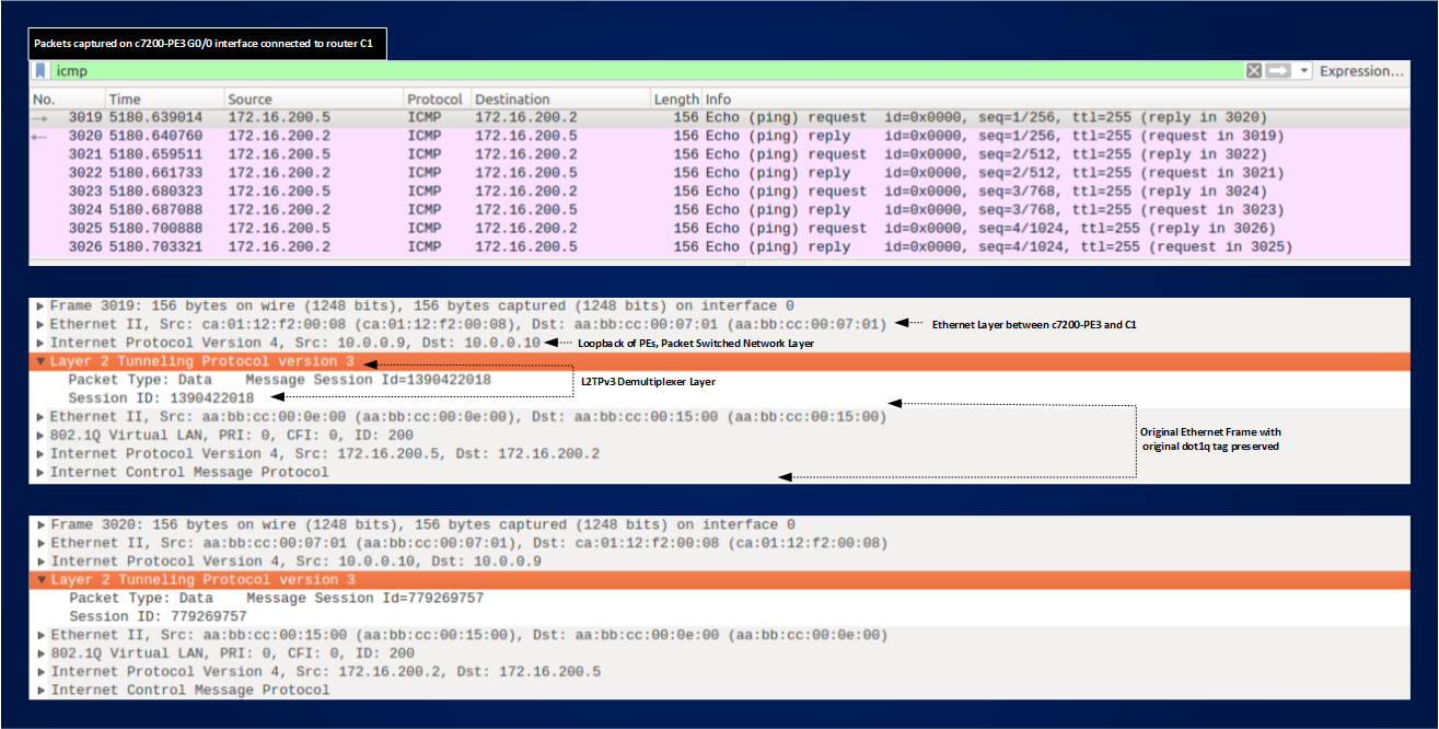
Encapsulation is quite simple, you take the original Ethernet Frame and put it under a L2TPv3 demultiplexer layer and an IP Header that realizes the Packet Switched Network Layer. Comparing MPLS pseudowire encapsulation and L2TPv3 pseudowire encapsulation, we can say that Outer Labels in MPLS PWs play the same role of the Packet Switched Network Layer in L2TPv3 pseudowire, this role is switching the encapsulated frame from the ingress PE to the Egress PE, in case of MPLS you swap a label hop-by-hop, in case of L2TPv3 you route an IP packet. Inner Labels, instead, has the same function of the Message Session ID in L2TPv3, they identifies PWs, in other words they demultiplex at egress PE the frame in such a way that it can be delivered to the correct exit interface, the function is called demultiplexing because under the same Outer Label or IP Header you can transport different Pseudowires.
To conclude this two-part-article I will show you a short example about using Pseudowires to transport something different from ethernet, I will establish PPP service between CE3-13 and CE3-24 using a an AToM Pseudowire and a L2TPv3 Pseudowire.
CE3-13 Serial4/0 goes toward a PE connected to MPLS core, and Serial4/1 goes toward a PE connected to the pure IP core, see here (https://wonderdam.altervista.org/blog/wp-content/uploads/2017/01/pwib-topology.png) the topology for reference.
I configured PPP like follows:
CE3-13#sh run int se4/0 | b interface
interface Serial4/0
ip address negotiated
encapsulation ppp
ppp chap hostname CE3S40
ppp chap password 0 @Serial40@
CE3-13#sh run int se4/1 | b interface
interface Serial4/1
ip address negotiated
encapsulation ppp
ppp chap hostname CE3S41
ppp chap password 0 @Serial41@
CE3-13 should receive its ip address by CE3-24 negotiating it via PPP. Serial4/0 of both devices will be connected via an AToM pseudowire and Serial4/1 will be connected via a L2TPv3 one.
CE3-24#show run int se4/0 | b interface
interface Serial4/0
ip address 192.168.0.1 255.255.255.252
encapsulation ppp
peer default ip address pool CE3S40
ppp authentication chap
CE3-24#show run int se4/1 | b interface
interface Serial4/1
ip address 192.168.0.5 255.255.255.252
encapsulation ppp
peer default ip address pool CE3S41
ppp authentication chap
CE3-24#sh run | s ip local
ip local pool CE3S40 192.168.0.2
ip local pool CE3S41 192.168.0.6
CE3-24#sh run | s username
username CE3S40 password 0 @Serial40@
username CE3S41 password 0 @Serial41@
Serial interfaces of PEs are configured as follows:
PE1#sh run int se4/0 | b interface
interface Serial4/0
no ip address
encapsulation ppp
serial restart-delay 0
xconnect 10.0.0.8 40 encapsulation mpls
c7200-PE4#sh run int se6/0 | b interface
interface Serial6/0
no ip address
encapsulation ppp
serial restart-delay 0
xconnect 10.0.0.7 40 encapsulation mpls
Pseudowire will go up signaled pw type this time will be PPP (0x0007)
PE1#show mpls l2transport vc 40
Local intf Local circuit Dest address VC ID Status
————- ————————– ————— ———- ———-
Se4/0 PPP 10.0.0.8 40 UP
c7200-PE4#show mpls l2transport vc 40
Local intf Local circuit Dest address VC ID Status
————- ————————– ————— ———- ———-
Se6/0 PPP 10.0.0.7 40 UP
Checking PPP service on CEs:
CE3-13#sh ppp all
Interface/ID OPEN+ Nego* Fail- Stage Peer Address Peer Name
———— ——————— ——– ————— ——————–
Se4/1 LCP* LCP 0.0.0.0
Se4/0 LCP+ IPCP+ CDPCP+ LocalT 192.168.0.1 CE3-24
CE3-13 receives the IP address from remote peer CE3-24:
CE3-13#show ip int br | ex una
Interface IP-Address OK? Method Status Protocol
Serial4/0 192.168.0.2 YES IPCP up up
I can ping:
CE3-13#ping 192.168.0.1
Type escape sequence to abort.
Sending 5, 100-byte ICMP Echos to 192.168.0.1, timeout is 2 seconds:
!!!!!
Success rate is 100 percent (5/5), round-trip min/avg/max = 30/31/33 ms
Configuration for the L2TPv3 case will be very similar except you need a pseudowire-class to specify encapsulation and IP local interface PEs must use:
c7200-PE3#sh run | s PPP
pseudowire-class PPP
encapsulation l2tpv3
ip local interface Loopback0
PE2#sh run | s PPP
pseudowire-class PPP
encapsulation l2tpv3
ip local interface Loopback0
c7200-PE3#sh run int se6/1 | b interface
interface Serial6/1
no ip address
encapsulation ppp
serial restart-delay 0
xconnect 10.0.0.10 41 pw-class PPP
PE2#sh run int se4/1 | b interface
interface Serial4/1
no ip address
encapsulation ppp
serial restart-delay 0
xconnect 10.0.0.9 41 encapsulation l2tpv3 pw-class PPP
c7200-PE3#show l2tun session
L2TP Session Information Total tunnels 1 sessions 2
LocID RemID TunID Username, Intf/ State Last Chg Uniq ID
Vcid, Circuit
63326191 2185942699 2911679334 200, Gi1/0.200:200 est 00:34:22 1
1179075689 2765371827 2911679334 41, Se6/1 est 00:00:25 5
NOTE: We should be familiar, after reading all this stuff, with seeing that the same Control Session (a.k.a Tunnel) signals both type of PW (ethernet, PPP).
c7200-PE3#show l2tun session circuit vcid 41
L2TP Session Information Total tunnels 1 sessions 2
LocID TunID Peer-address Type Stat Username, Intf/
Vcid, Circuit
1179075689 2911679334 10.0.0.10 PPP UP 41, Se6/1
PE2#show l2tun session
L2TP Session Information Total tunnels 1 sessions 2
LocID RemID TunID Username, Intf/ State Last Chg Uniq ID
Vcid, Circuit
2185942699 63326191 3749426641 200, Et0/1.200:200 est 01:03:44 0
2765371827 1179075689 3749426641 41, Se4/1 est 00:04:41 0
PE2#show l2tun session circuit vcid 41
L2TP Session Information Total tunnels 1 sessions 2
LocID TunID Peer-address Type Stat Username, Intf/
Vcid, Circuit
2765371827 3749426641 10.0.0.9 PPP UP 41, Se4/1
CE3-13 receives its IP address for interface Se4/1 and can ping remote peer:
CE3-13#show ppp all
Interface/ID OPEN+ Nego* Fail- Stage Peer Address Peer Name
———— ——————— ——– ————— ——————–
Se4/1 LCP+ IPCP+ CDPCP+ LocalT 192.168.0.5 CE3-24
Se4/0 LCP+ IPCP+ CDPCP+ LocalT 192.168.0.1 CE3-24
CE3-13#show ip int br | ex una
Interface IP-Address OK? Method Status Protocol
Serial4/0 192.168.0.2 YES IPCP up up
Serial4/1 192.168.0.6 YES IPCP up up
CE3-13#ping 192.168.0.5
Type escape sequence to abort.
Sending 5, 100-byte ICMP Echos to 192.168.0.5, timeout is 2 seconds:
!!!!!
Success rate is 100 percent (5/5), round-trip min/avg/max = 22/29/32 ms
CE3-13#
This test concludes this article.