Section 1 – AToM Pseudowire.
In this article I want to summarize some definitions that are the foundations to understand Pseudowire Emulation and L2VPN service with more attention to Ethernet Pseudowire Emulation.
When I approached L2VPN theory for the first time I was quite overwhelmed by the terminology, because reading different sources of information (Pseudowire Emulation Edge to Edge (pwe3) IETF Working Group, RFCs, Metro Ethernet Forum definitions) similar concepts were described using, sometimes, different words, then I decided to clear my ideas writing something to summarize all these concepts.
To start let’s try to recap how a L2VPN service could be defined.
A Layer 2 Virtual Private Network Service can be seen as mechanism to transport a Layer 2 Frame over either a pure IP or MPLS core. The problem we are trying to solve is to connect two or more remote devices located in geographically dispersed areas, in a transparent way, as if the devices were directly connected by a physical circuit.
The fundamental element to establish such a service is the PSEUDOWIRE. Let’s see how it is defined.
From RFC3985 (1.1 Pseudowire Definition) and RFC 3916 (1.1 What are Pseudowires?) its definition is:
“PWE3 is a mechanism that emulates the essential attributes of a telecommunications service (such as a T1 leased line or Frame Relay) over a Packet Switched Network (PSN). PWE3 is intended to provide only the minimum necessary functionality to emulate the wire with the required degree of faithfulness for the given service definition. From the perspective of Customer Edge Equipment (CE), the PW is characterized as an unshared link or circuit of the chosen service.”
From RFC4026 its definition is:
“A pseudowire is an emulated point-to-point connection over a packet switched network that allows the interconnection of two nodes with any L2 technology.“
Layer 2 VPN Architectures uses the same definitions I found in RFCs mentioned above, but summarizing other important characteristics about transparency of the service and a more practical definition:
TRANSPARENCY ==> “To end customers and their devices, it is transparent that the circuit service is provided through pseudowire emulation”
“A pseudowire is a virtual circuit between two PE devices that interconnects two attachment circuits.” This last definition comes from the reference network model for pseudowire emulation as shown in the following picture:
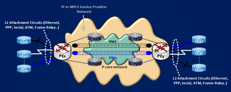
Keeping good the last practical definition, to move on we need to know what is an ATTACHMENT CIRCUIT, again from RFC3985 we can read:
“Attachment Circuit (AC) is The physical or virtual circuit attaching a CE to a PE. An attachment Circuit may be, for example, a Frame Relay DLCI, an ATM VPI/VCI, an Ethernet port, a VLAN, a PPP connection on a physical interface, a PPP session from an L2TP tunnel, or an MPLS LSP.”
The most raw representation of a L2VPN service could be:
![]()
Next move to reach the target of connecting transparently 2 CE devices is associating the Attachment Circuits with the Pseudowire connecting them. Here we have two choices based on the nature of the Service Provider Core.
If the core is MPLS enabled, you will have a service called Any Transport over MPLS (AToM), the Pseudowire will be formed by two unidrectional Label Switched Paths (LSPs), and the tools used to represent a pseudowire are LDP Labels and the Pseudowire ID FEC Element. The logic is, Pseudowire ID FEC Element is a LDP data structure containing a Pseudowire ID, shared by the two remote PEs, that identifies the Virtual Channel connecting the two remote ACs, a Label Mapping Message is then used to map each AC to the Pseudowire.
If the core is only IP enabled (not MPLS), we can establish L2TPv3 Pseudowires, in this case:
– the protocol itself uses an in band control mechanism creating a Control Session a.k.a l2tun tunnel in IOS terms.
– this Control Session is identified by a [Local Tunnel ID (LocTunID), Remote Tunnel ID (RemTunID)] pair.
– the created Control Session is used to signal every Pseudowires, that are called Sessions in IOS terms.
– Every Pseudowires is then identified by a [Local ID (LocID), Remote ID (RemID)] pair.
The type of Pseudowire (AToM, or L2TPv3) defines the encapsulation of the original frame inside the Pseudowires.
To understand this basic concepts I set up this small network and I capture the relevant packets flowing on it.
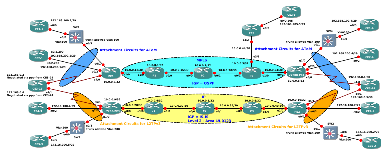
Let’ start with the first example. CE1-1 and CE1-4 need to connect on VLAN100. VLAN100 arrives at PEs PE1 and c7200-PE4 via trunk interfaces that allow only this vlan:
CE1-1#sh run int e0/0 | b interface
interface Ethernet0/0
ip address 192.168.100.1 255.255.255.248
SW1#sh run int e0/1 | b interface
interface Ethernet0/1
switchport trunk encapsulation dot1q
switchport trunk allowed vlan 100
switchport mode trunk
SW4#show run int e0/1 | b interface
interface Ethernet0/1
switchport trunk encapsulation dot1q
switchport trunk allowed vlan 100
switchport mode trunk
CE1-4#show run int e0/0 | b interface
interface Ethernet0/0
ip address 192.168.100.4 255.255.255.248
With this configuration ethernet frames arriving at PEs are dot1q frames containing a VLAN tag. PEs needs then to match them using a dot1q subinterfaces, in this case, then, Attachment Circuits are dot1q subinterfaces.
PE1#sh run int e0/1.100 | b interface
interface Ethernet0/1.100
encapsulation dot1Q 100
shutdown
c7200-PE4#show run int g1/0.100 | b interface
interface GigabitEthernet1/0.100
encapsulation dot1Q 100
shutdown
From a configuration point of view establishing a point-to-point pseudowire is simple, the command to use is “xconnect” under the subinterfaces that are connected to each ACs. This is the configuration:
PE1#sh run int e0/1.100 | b interface
interface Ethernet0/1.100
encapsulation dot1Q 100
shutdown
xconnect 10.0.0.8 100 encapsulation mpls
c7200-PE4#sh run int g1/0.100 | b interface
interface GigabitEthernet1/0.100
encapsulation dot1Q 100
shutdown
xconnect 10.0.0.7 100 encapsulation mpls
The sintax of the xconnect command is: xconnect “Loopback IP address of remote peer PE” “Virtual Channel Identifier (Pseudowire ID)” “type of encapsulation”. Here the VC ID selected is 100, and encapsulation must be MPLS if you want an AToM service (the other type you can specify is L2TPv3).
Now, as summarized above, an AToM Pseudowire is formed by TWO unidirectional (going in opposite directions between the two peering PEs) Label Switch Paths (LSPs). This paths are established by IGP/LDP running in the service provider core and are the LSPs that allow to reach the Loopback of the remote PEs. This path at each PE will be identified by an MPLS label and this label will be the OUTER LABEL (a.k.a TUNNEL LABEL) of the two levels MPLS stack forming the Pseudowire encapsulation. The second label (the INNER LABEL a.k.a VC Label or Pseudowire Label) it’s also established by LDP, but this time will be a TARGETED LDP SESSION between the 2 remote PEs to define the label. Let’s try to recap:
For AToM Pseudowire, LDP is the out of band signaling protocol, LDP it’s used inside the Service Provider Core (as for any other MPLS application) to give us an LSP path between the loopbacks of the peering PEs, and in a Targeted Session between the PEs to give us the MPLS Label that identifies the Pseudowire. The MPLS Pseudowire Encapsulation can be represented as shown here:
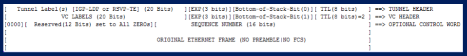
NOTE: It’s Possible to use MPLS/Traffic-Engineering (TE) as Label Switched Path in the Service Provider Core, in this case the Outer Label will be the one established by RSVP/TE to identify the Traffic-Engineering path. If you want to read more about that I wrote some example here .
Let’s see which is the IGP/LDP path in this example.
I constrained the MPLS LABEL SPACE on each router so it’s easy to read the assigned labels.
P1 ==> will assign labels in the space 1000 – 1999
P2 ==> will assign labels in the space 2000 – 2999
P3 ==> will assign labels in the space 3000 – 3999
PE1 ==> will assign labels in the space 11000 – 11999
c7200-PE4 ==> will assign labels in the space 44000 – 44999
PE1#traceroute 10.0.0.8 source 10.0.0.7
Type escape sequence to abort.
Tracing the route to 10.0.0.8
VRF info: (vrf in name/id, vrf out name/id)
1 10.0.0.13 [MPLS: Label 1001 Exp 0] 7 msec 9 msec 10 msec
2 10.0.0.18 [MPLS: Label 2001 Exp 0] 11 msec 10 msec 10 msec
3 10.0.0.22 [MPLS: Label 3002 Exp 0] 1 msec 1 msec 1 msec
4 10.0.0.26 28 msec 10 msec 10 msec
c7200-PE4#traceroute 10.0.0.7 source 10.0.0.8
Type escape sequence to abort.
Tracing the route to 10.0.0.7
VRF info: (vrf in name/id, vrf out name/id)
1 10.0.0.25 [MPLS: Label 3003 Exp 0] 12 msec 8 msec 8 msec
2 10.0.0.21 [MPLS: Label 2002 Exp 0] 12 msec 8 msec 12 msec
3 10.0.0.17 [MPLS: Label 1000 Exp 0] 12 msec 12 msec 8 msec
4 10.0.0.14 12 msec 8 msec 12 msec
It’s easy to see the LSPs. From PE1 to c7200-PE4 ==> 1001 -> 2001 -> 3002. In the opposite direction ==> 3003 -> 2002 -> 1000
From the shows above you can see that Attachment Circuits at both PEs are in shutdown then there is no VC Label already assigned to Pseudowire 100, you can verify this with this show:
PE1#show mpls l2transport vc 100 detail
Local interface: Et0/1.100 admin down, line protocol down, Eth VLAN 100 admin down
Destination address: 10.0.0.8, VC ID: 100, VC status: admin down
Last error: Local access circuit is not ready for label advertise
Output interface: none, imposed label stack {}
Preferred path: not configured
Default path: no route
No adjacency
Create time: 01:32:05, last status change time: 01:35:33
Last label FSM state change time: 01:29:22
Signaling protocol: LDP, peer 10.0.0.8:0 up
Targeted Hello: 10.0.0.7(LDP Id) -> 10.0.0.8, LDP is UP
c7200-PE4#show mpls l2transport vc 100 detail
Local interface: Gi1/0.100 admin down, line protocol down, Eth VLAN 100 admin down
Destination address: 10.0.0.7, VC ID: 100, VC status: down
Output interface: none, imposed label stack {}
Preferred path: not configured
Default path: no route
No adjacency
Create time: 01:32:04, last status change time: 01:32:04
Signaling protocol: LDP, peer 10.0.0.7:0 up
Targeted Hello: 10.0.0.8(LDP Id) -> 10.0.0.7
We can easily see that “VC status is admin down”, last reported error tell us that AC is not ready for label advertisement, the imposed label stack is empty, but we can see that the targeted LDP session is up because this happens as soon as you configure the xconnect command and there is IP/MPLS reachability between the Loopbacks of the peering PEs. Then, last thing I have to do to establish the pseudowire is activating the Attachment Circuits, that is removing shutdown from the subinterfaces.
PE1(config)#int e0/1.100
PE1(config-subif)#no shut
c7200-PE4(config)#int g1/0.100
c7200-PE4(config-subif)#no shut
After some messages exchange, the final status of the pseudowire is:
PE1#show mpls l2transport vc 100
Local intf Local circuit Dest address VC ID Status
————- ————————– ————— ———- ———-
Et0/1.100 Eth VLAN 100 10.0.0.8 100 UP
c7200-PE4#show mpls l2transport vc 100
Local intf Local circuit Dest address VC ID Status
————- ————————– ————— ———- ———-
Gi1/0.100 Eth VLAN 100 10.0.0.7 100 UP
Before going deeper into the details of the packets I captured, let’s see which are the imposed label stacks:
PE1#show mpls l2transport vc 100 detail | i Local|stack
Local interface: Et0/1.100 up, line protocol up, Eth VLAN 100 up
Output interface: Et1/0, imposed label stack {1001 44007}
c7200-PE4#show mpls l2transport vc 100 detail | i Local|stack
Local interface: Gi1/0.100 up, line protocol up, Eth VLAN 100 up
Output interface: Gi0/0, imposed label stack {3003 11008}
Looking at these outputs we know that our Pseudowire packets exiting the interface of the PE looking at the MPLS core will have two labels on the top of the original frames:
[1001(Tunnel Label)][44007(VC Label/PW Label)][Control Word][Original Ethernet Frame] P1 ==> c7200-PE4
[3003(Tunnel Label)][11008(VC Label/PW Label)][Control Word][Original Ethernet Frame] c7200-PE4 ==> P1
Following picture shows how the labels are inserted and switched on the packets and should give you an idea about what is an AToM Pseudowire.
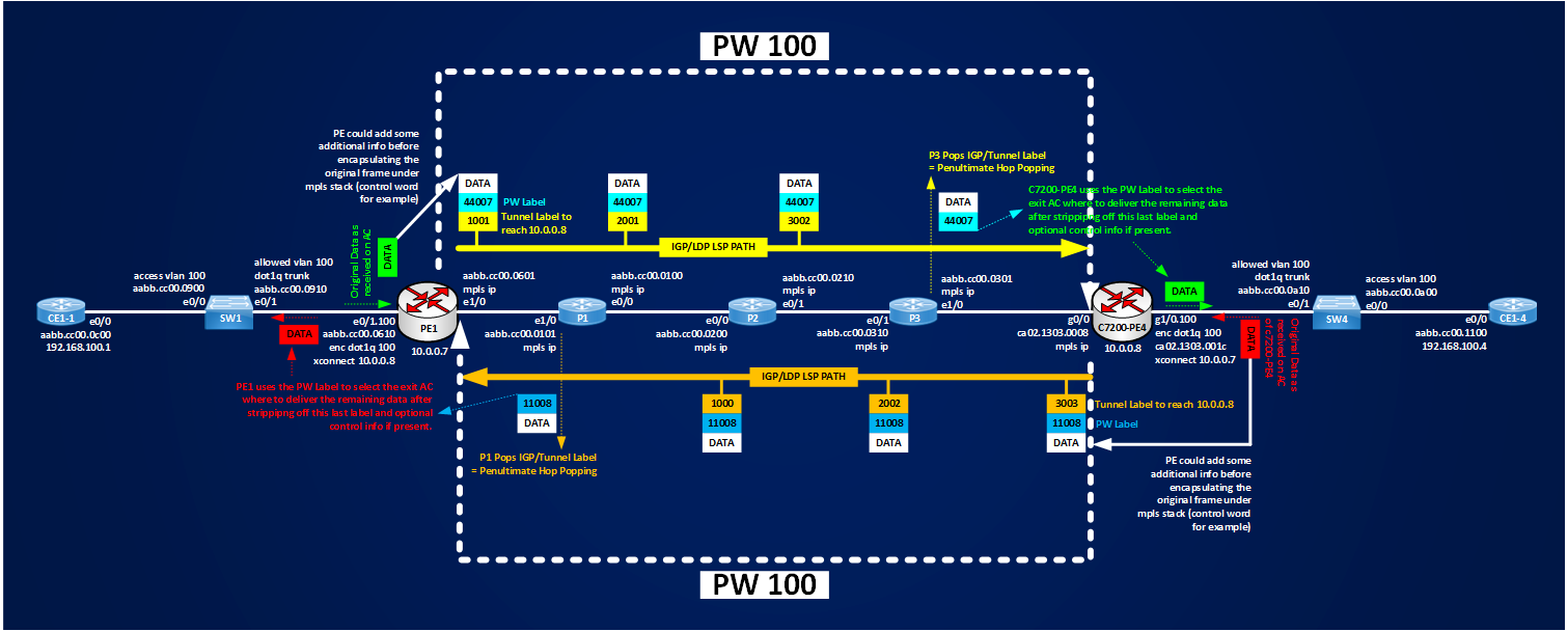
We can summarize that an AToM Pseudowire is made of two unidirectional LSPs and that the original data is encapsulated in the pseudowire using a two-level label stack, where the inner label (VC Label or PW Label) is established via Targeted Ldp as soon as ACs are active and it identifies the Pseudowire itself, and an outer label (Tunnel Label) that is used by MPLS Core to switch the pseudowire packet down to the egress PE where original data is finally delivered.
Now, let’s see how the real packet are looking at some details. The following figure shows how PE1 and c7200-PE4 exchange LDP targeted messages:
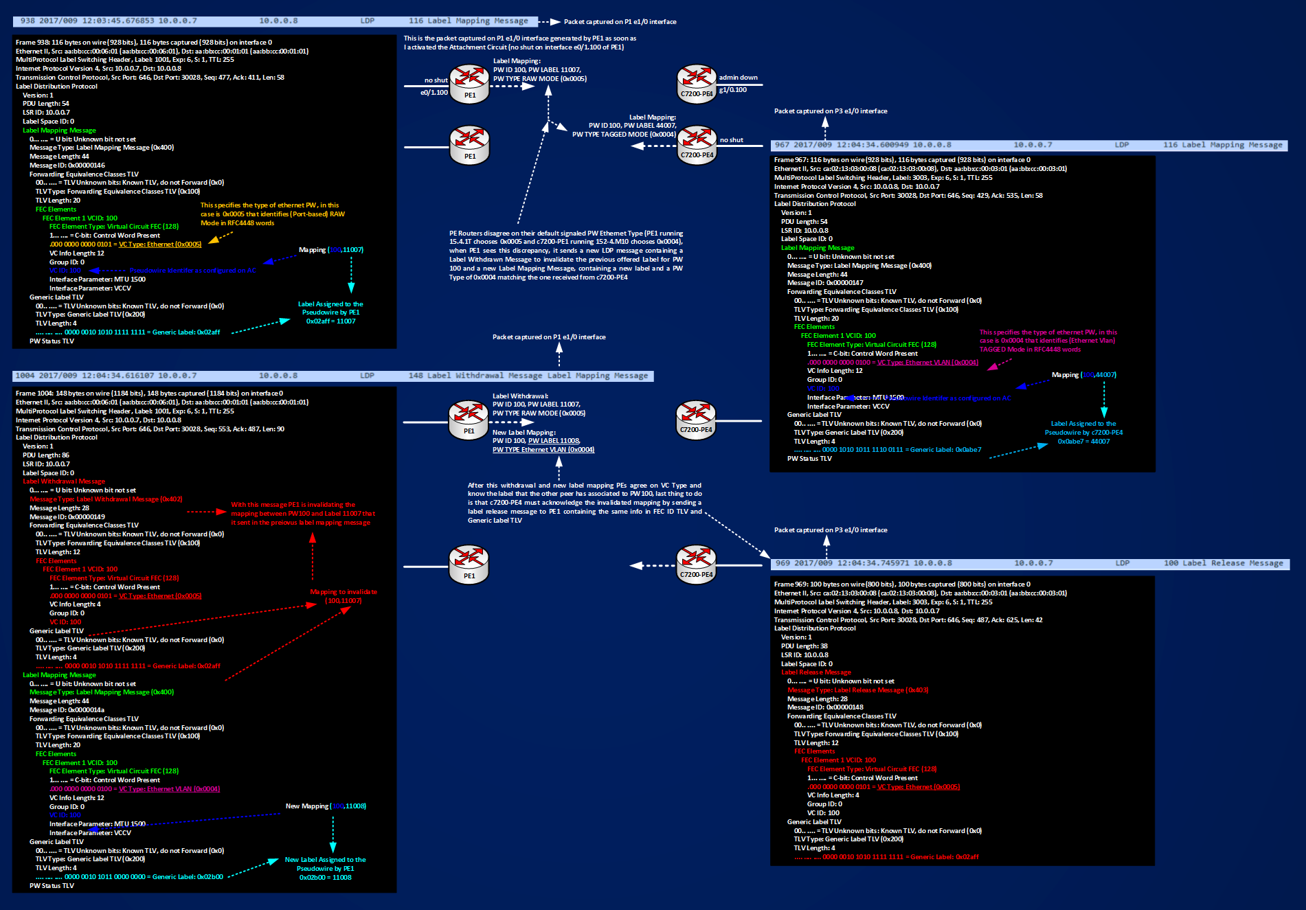
In the figure you can see that there is an exchange of 4 LDP Message between PE routers:
PE1 ==> c7200-PE4 Label Mapping Message (frame 938 captured on P1 e1/0 interface) ==> Advertised Mapping [Label 11007, PW100, PW TYPE RAW MODE (0x0005)]
c7200-PE4 ==> PE1 Label Mapping Message (frame 967 captured on P3 e1/0 interface) ==> Advertised Mapping [Label 44007, PW100, PW TYPE Ethernet VLAN MODE (0x0004)]
PE1 ==> c7200-PE4 Label Withdrawal + Label Mapping Message (frame 1004 captured on P1 e1/0 interface) ==> Invalidated Mapping (11007,100,PW TYPE 0x0005)+New Mapping (11008,100,PW TYPE 0x0004)
c7200-PE4 ==> PE1 Label Release Message (frame 969 captured on P3 e1/0 interface) ==> Ok I Understood not using label 11007
Looking at the details of the LDP message exchange helps to understand how the PEs come to an agreement about which labels to use for the advertised PW 100, the interesting thing to notice is that by default two different platforms (though virtual) using two different IOS, have a different behavior when they advertise the configured Pseudowire, one select 0x0005 for RAW MODE, the other peer selects 0x0004 for TAGGED MODE, then it’s very important to test the basic operations before deploying new services to avoid conflicting PW Types. Here routers find an agreement in automatic way, if you are using equipment from different vendors maybe this doesn’t happen despite the fact that each vendor declares that they are RFC compliant.
Now I want to spend some time about what really are the 2 different pseudowire types mode, RAW MODE (0x0005) and TAGGED MODE (0x0004) see IANA assigned type numbers here. When I read RFC4448 for the first time, reaching the section that describes raw mode and tagged mode, I was quite confused because it defines this types adding the concepts of service-delimiting tags and not-service-delimiting tags. Looking at the errata of the RFC I found that already someone else was confused like me (se errata here).
From the first test described above, I know that PE1 and c7200-PE4 found an agreement to use Type 0x0004 Tagged Mode, let’s send some data traffic over the PW and let’s see what happens. I will simply send a ping from CE1-1 to CE1-4. Before sending some pings arp tables of the remote CEs contains only their IP/MAC:
CE1-1#show ip arp
Protocol Address Age (min) Hardware Addr Type Interface
Internet 192.168.100.1 – aabb.cc00.0c00 ARPA Ethernet0/0
CE1-4#show ip arp
Protocol Address Age (min) Hardware Addr Type Interface
Internet 192.168.100.4 – aabb.cc00.1100 ARPA Ethernet0/0
Pinging confirms that L2VPN service is working:
CE1-1#ping 192.168.100.4
Type escape sequence to abort.
Sending 5, 100-byte ICMP Echos to 192.168.100.4, timeout is 2 seconds:
.!!!!
Success rate is 80 percent (4/5), round-trip min/avg/max = 20/21/22 ms
ARP tabels are now populated with the MAC of the remote CE:
CE1-1#sh ip arp
Protocol Address Age (min) Hardware Addr Type Interface
Internet 192.168.100.1 – aabb.cc00.0c00 ARPA Ethernet0/0
Internet 192.168.100.4 0 aabb.cc00.1100 ARPA Ethernet0/0
CE1-4#show ip arp
Protocol Address Age (min) Hardware Addr Type Interface
Internet 192.168.100.1 0 aabb.cc00.0c00 ARPA Ethernet0/0
Internet 192.168.100.4 – aabb.cc00.1100 ARPA Ethernet0/0
Below you can see the captured pings:
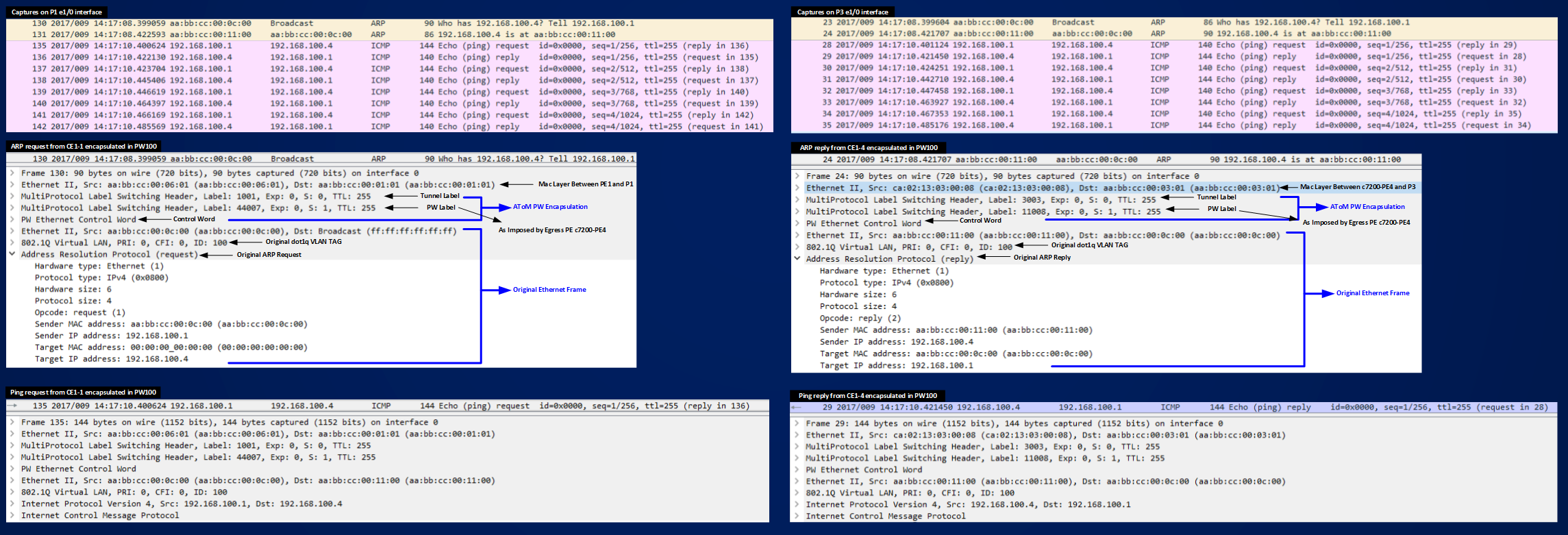
Figure shows how data packets (ARP request/reply and ICMP requests/replies) are encapsulated with a two level label stack and we see also how the PEs, after the agreement to use PW TYPE 0x0004 preserve the Original dot1q tag and transport it transparently to the egress PEs.
Now, if you read RFC4448 when you reach section 4.4.1 is where things become foggy about transporting/preserving Vlan Tags, service-delimiting or not-service-delimiting tags and pseudowire types.
RFC448 says: “When the PE receives an Ethernet frame, and the frame has a VLAN tag, we can distinguish two cases:
1. The tag is service-delimiting.
“This means that the tag was placed on the frame by some piece of service provider-operated equipment, and the tag is used by the service provider to distinguish the traffic.”
2. The tag is not service-delimiting.
“This means that the tag was placed in the frame by a piece of customer equipment, and is not meaningful to the PE.”
RFC4448 then continues: “Whether or not the tag is service-delimiting is determined by local configuration on the PE. If an Ethernet PW is operating in tagged mode, every frame sent on the PW MUST have a service-delimiting VLAN tag. If the frame as received by the PE from the attachment circuit does not have a service-delimiting VLAN tag, the PE must prepend the frame with a dummy VLAN tag before sending the frame on the PW. This is the default operating mode. This is the only REQUIRED mode.”
And more: “In both modes, not-service-delimiting tags are passed transparently across the PW as part of the payload.” and:
“When tagged mode is used, the PE that receives a frame from the PW may rewrite the tag value, or may strip the tag entirely, or may leave the tag unchanged, depending on its configuration. When raw mode is used, the PE that receives a frame may or may not need to add a service-delimiting tag before transmitting the frame on the attachment circuit; however, it MUST not rewrite or remove any tags that are already present.”
Then the section conclude with this summary table:

Confused like me? I understand you.
Now, to clear someway the fog, in my example who puts the dot1q tag on the frame is the switch SW1, I have not specified if SW1 is operated by the customer or by the SP. Let’s suppose it’s a switch operated by the customer. The important thing to understand is how PEs operates based on their default and not-default configuration. From example above I know that PE1 and c7200-PE4 agree to use PW 100 in Tagged Mode and that they transparently preserve the tag of the encapsulated frame as seen in the captured packets.
Let’s activate another PW on the network. This time the ACs to connect are the link connected to PE1 e0/2 interface and c7200-PE4 g2/0 interface.
Just a silly example I configured CEs and PEs like you can see here:
CE2-1#sh run int e0/2.200 | b interface
interface Ethernet0/2.200
encapsulation dot1Q 200
ip address 192.168.200.1 255.255.255.248
PE1#sh run int e0/2 | b interface
interface Ethernet0/2
no ip address
xconnect 10.0.0.8 200 encapsulation mpls
c7200-PE4#sh run int g2/0 | b interface
interface GigabitEthernet2/0
no ip address
xconnect 10.0.0.7 200 encapsulation mpls
CE2-4#sh run int e0/2.200 | b interface
interface Ethernet0/2.200
encapsulation dot1Q 200
ip address 192.168.200.4 255.255.255.248
The difference with the first example is that xconnect commands are configured under the physical interfaces on PEs and not on dot1q subinterfaces:
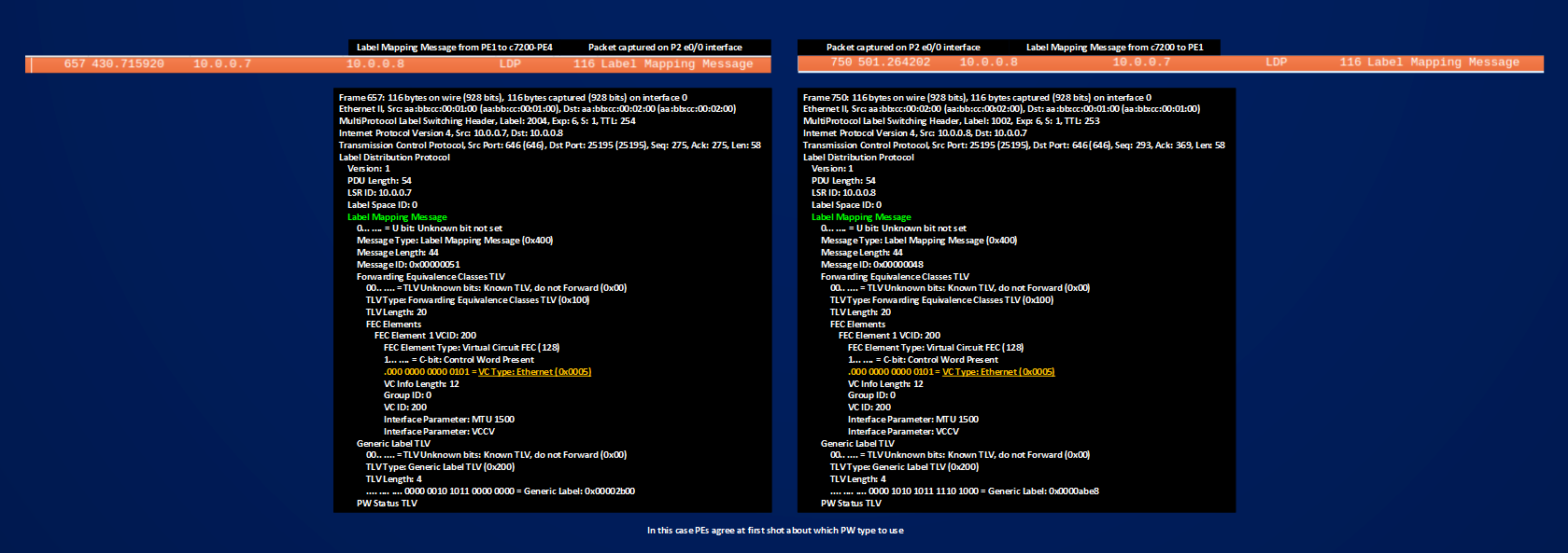
In the figure above you can see that this time PEs agree at first shot about which pseudowire type to use (Ethernet RAW Mode 0x0005), this because c7200-PE4 when having a PW configured on its physical interface signal this type of pseudowire by default (and not a tagged one), for PE1 instead nothing changes it signals 0x0005 as in the first case; let’s check if something changes in the transported frame:
CE2-1#show ip arp
Protocol Address Age (min) Hardware Addr Type Interface
Internet 192.168.200.1 – aabb.cc00.0b20 ARPA Ethernet0/2.200
CE2-1#ping 192.168.200.4
Type escape sequence to abort.
Sending 5, 100-byte ICMP Echos to 192.168.200.4, timeout is 2 seconds:
.!!!!
Success rate is 80 percent (4/5), round-trip min/avg/max = 17/20/25 ms
PW 200 is operational.
PE1#show mpls l2transport vc 200
Local intf Local circuit Dest address VC ID Status
————- ————————– ————— ———- ———-
Et0/2 Ethernet 10.0.0.8 200 UP
c7200-PE4#show mpls l2transport vc 200
Local intf Local circuit Dest address VC ID Status
————- ————————– ————— ———- ———-
Gi2/0 Ethernet 10.0.0.7 200 UP
Note the difference on the type of ACs reported in the outputs. See the ping packet here:
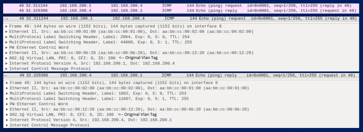
From a Transported frame point of view there is no difference between the two cases, both PW Type 0x0004 and 0x0005 leave intact the original ethernet dot1q tagged frame.
Let’s build another test, PE5 runs the same IOS of PE1 and CE2-5 is connected to it. Then I have configured CE2-1 with a new dot1q subinterface that add tags for VLAN205:
CE2-1#sh run int e0/2.205 | b interface
interface Ethernet0/2.205
encapsulation dot1Q 205
ip address 192.168.205.1 255.255.255.248
PE1#show run int e0/2.205 | b interface
interface Ethernet0/2.205
encapsulation dot1Q 205
xconnect 10.0.0.11 205 encapsulation mpls
PE5#sh run int e0/0.205 | b interface
interface Ethernet0/0.205
encapsulation dot1Q 205
xconnect 10.0.0.7 205 encapsulation mpls
CE2-5#show run int e0/0.205 | b interface
interface Ethernet0/0.205
encapsulation dot1Q 205
ip address 192.168.205.5 255.255.255.248
Find below the captured label mapping messages and icmp ping.
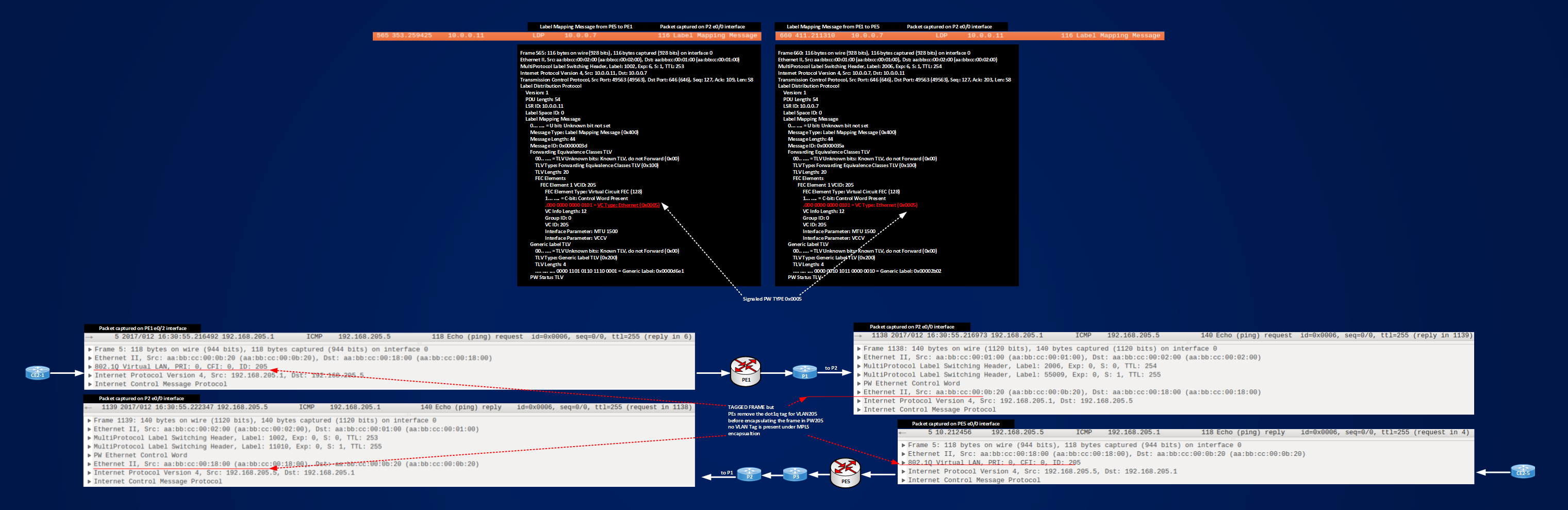
In the figure you can see that we have a Pseudowire Type 0x0005, and that the Original Vlan Tag for VLAN205 is removed by PE1 and PE5 before encapsulating the frame inside the pseudowire.
Let’s recap three tests made until now:
1] PW100, original frame coming to PE1 dot1q tagged, PE1 running IOS 15.41T, peering PE a 7200 router running 152-4.M10, xconnect commands configured under dot1q subinterfaces matching the VLAN Tag of the frame coming in from the Attachment Circuit. With this set-up PE1 signal by default PW Type 0x0005 (RAW MODE), 7200 router signal a PW Type 0x0004 (Ethernet Vlan), after finding an agreement via LDP Label Mapping/Release messages, routers use PW Type 0x0004 and the final result is that original tagged frame are transported transparently with their tags inside PW100.
Summary Info for PW100 are:
PE1#show mpls l2transport vc 100 detail | i Local|Destination|Interworking
Local interface: Et0/1.100 up, line protocol up, Eth VLAN 100 up
Destination address: 10.0.0.8, VC ID: 100, VC status: up
2] PW200, original frame coming to PE1 dot1q tagged, PE1 running IOS 15.41T, peering PE a 7200 router running 152-4.M10, xconnect commands configured under physical interfaces of the PEs connected to the ACs. With this setup both PEs signals the same PW TYPE 0x0005 and the final result is that original tagged frames are transported transparently with their tags inside PW200.
Sumamry info for PW200 are:
PE1#show mpls l2transport vc 200 detail | i Local|Destination|Interworking
Local interface: Et0/2 up, line protocol up, Ethernet up
Destination address: 10.0.0.8, VC ID: 200, VC status: up
3] PW205, original frame coming to PE1 dot1q tagged, both peering PEs (PE1 and PE5) running IOS 15.41T, xconnect commands configured under dot1q subinterfaces matching the VLAN Tag of the frame coming in from the Attachment Circuit. With this setup both PEs signals the same PW TYPE 0x0005 and the final result is that dot1q tags present on original frames are stripped off by ingress PEs before the frames are encapsulating in Pseudowires.
Summary info for PW205 are:
PE1#show mpls l2transport vc 205 detail | i Local|Destination|Interworking
Local interface: Et0/2.205 up, line protocol up, Eth VLAN 205 up
Interworking type is Ethernet
Destination address: 10.0.0.11, VC ID: 205, VC status: up
Now, looking at outputs of “show mpls l2transport ..” for the three cases, we can see that in the 3rd case output match a info that is not present in the previous 2 cases, this info is:
==> Interworking Type is Ethernet
The interworking type is a mechanism local to each PE that tells PE how to operate on the tag of the received frame before encapsulating it under pseudowire encapsulation and then which PW TYPE to advertise. A pseudowire will be established if interworking types match at both peering PEs and this should be grant consistency of the L2VPN service.
Two types of ethernet interworking exists: Ethernet and VLAN.
Ethernet means advertising a PW TYPE 0x0005 (RAW MODE) and tells the PE either to strip off the first Vlan Tag (if present) on the received frame, or make nothing on it.
VLAN means advertising a PW TYPE 0x0004 (TAGGED MODE) and tells the PEs either to preserve all the tags that are already present on the received frame, or adding/rewriting the frame but not removing the tags that are already present.
For example in case 1] PE1 uses a default interworking type that is Ethernet and signals a PW TYPE 0x0005, c7200-PE4 uses a default interworking type that is VLAN and signals a PW TYPE of 0x0004, when the PEs see that they don’t agree PE1 lets c7200-PE4 to win and then they end up with using PW TYPE 0x0004 and tags are preserved.
Some confusion may arise looking at the outputs, because based upon which IOS you are using, different default behavior are running and different default/not-default information are shown.
The core concept to understand here is that you must be able to control the local operation made by the PEs on the received frames to have a consistent L2VPN service.
Case 1] can be summarized as TAGGED MODE 0x0004 – ORIGINAL TAGS ARE PRESERVED ==> This could match the case “service-delimiting tag, tagged mode” in RFC4448 terms
Case 2] can be summarized as RAW MODE 0x0005 – ORGINAL TAGS ARE PRESERVED ==> This could match the case “no service-delimiting tag, raw mode” in RFC4448 terms
Case 3] can be summarized as RAW MODE 0x0005 – ORIGINAL TAGS ARE STRIPPED OFF ==> This could match the case “service-delimiting, raw mode” in RFC4448 terms
I will come back later on service-delimiting not-service-delimiting concepts.
The best option, in my opinion, is to control manually what the PEs do, instead of trusting their default behavior. The tool to control Interworking Type (and then the type of local operation made on the frames received on each local attachment circuit) is a PSEUDOWIRE-CLASS:
PE1(config)#pseudowire-class TEST
PE1(config-pw-class)#?
Pseudowire-class configuration commands:
default Set a command to its defaults
encapsulation Data encapsulation method
exit Exit from Pseudowire-class configuration mode
no Negate a command or set its defaults
PE1(config-pw-class)#encapsulation ?
l2tpv2 Use L2TPv2 encapsulation
l2tpv3 Use L2TPv3 encapsulation
mpls Use MPLS encapsulation
PE1(config-pw-class)#encapsulation mpls ?
<cr>
PE1(config-pw-class)#interworking ?
ethernet Ethernet interworking
ip IP interworking
vlan VLAN interworking
A pseudowire-class is a sort of template where you can define pseudowire features that can be commonly invoked by the xconnect command that define the Pseudowire.
Encapsulation mode defines the type of PW (mpls for AToM and L2TPv3), when you choose encapsulation mpls then you can define interworking type, for AToM the two options are:
ethernet ==> for 0x0005 RAW MODE service
vlan ==> for 0x0004 TAGGED MODE service
Now look the same for the 7200 router:
c7200-PE4(config)#pseudowire-class TEST
c7200-PE4(config-pw-class)#encapsulation mpls
c7200-PE4(config-pw-class)#interworking ?
ethernet Ethernet interworking
ip IP interworking
For the 7200 router we have not the vlan option, why? Because for this platform and IOS, used VLAN TAGGED MODE is the default one. Now, let’s try to reproduce the same results of case 1] (PW TYPE 0x0004 Tagged Mode, preserving vlan tags) using a pseudowire-class on PE1:
PE1#sh run | s pseudowire-class PW100
pseudowire-class PW100
encapsulation mpls
interworking vlan
PE1#sh run int e0/1.100 | b interface
interface Ethernet0/1.100
encapsulation dot1Q 100
xconnect 10.0.0.8 100 encapsulation mpls pw-class PW100
c7200-PE4 configuration will remain the same:
c7200-PE4#sh run int G1/0.100 | b interface
interface GigabitEthernet1/0.100
encapsulation dot1Q 100
xconnect 10.0.0.7 100 encapsulation mpls
PW100 is active:
PE1#show mpls l2transport vc 100
Local intf Local circuit Dest address VC ID Status
————- ————————– ————— ———- ———-
Et0/1.100 Eth VLAN 100 10.0.0.8 100 UP
c7200-PE4#sh mpls l2transport vc 100
Local intf Local circuit Dest address VC ID Status
————- ————————– ————— ———- ———-
Gi1/0.100 Eth VLAN 100 10.0.0.7 100 UP
The true difference with case 1] is how PE1 signals its PW TYPE, in this case it signals directly a PW TYPE 0x0004 and not the default 0x0005, then the label mapping message exchange will be simply:
1] PE1 ==> to c7200-PE4: LABEL MAPPING MESSAGE (PW100, my label is 11011, PW TYPE 0x0004 TAGGED MODE)
2] c7200-PE4 ==> to PE1: LABEL MAPPING MESSAGE (PW100, my label is 44000, PW TYPE 0x0004 TAGGED MODE)
Instead of the one in case 1] that I re-summarize here:
1] PE1 ==> to c7200-PE4: LABEL MAPPING MESSAGE (PW100, my label is 11007, PW TYPE 0x0005 RAW MODE)
2] c7200-PE4 ==> to PE1: LABEL MAPPING MESSAGE (PW100, my label is 44007, PW TYPE 0x0004 TAGGED MODE)
3] PE1 ==> to c7200-PE4: LABEL WITDRAWAL MESSAGE (PW100, invalidate label 11007, PW TYPE 0x0005 RAW MODE), LABEL MAPPING MESSAGE (PW100, my new label is 11008, PW TYPE 0x0004 TAGGED MODE)
4] c7200-PE4 ==> to PE1: LABEL RELEASE MESSAGE (PW100, label 11007 is invalidated, PW TYPE 0x0005 RAW MODE)
As a last example I modify PW205 working between the same type of PEs (running IOS 15.41T), in case 3] we saw that they signal PW TYPE 0x0005 by default and strip off the received tag, here instead I will use a pw-class to use a PW TYPE of 0x0004 and preserving tags.
PE1#sh run | s pseudowire-class PW205
pseudowire-class PW205
encapsulation mpls
interworking vlan
PE1#sh run int e0/2.205 | b interface
interface Ethernet0/2.205
encapsulation dot1Q 205
xconnect 10.0.0.11 205 encapsulation mpls pw-class PW205
PE5#show run | s pseudowire-class PW205
pseudowire-class PW205
encapsulation mpls
interworking vlan
PE5#sh run int e0/0.205 | b interface
interface Ethernet0/0.205
encapsulation dot1Q 205
xconnect 10.0.0.7 205 encapsulation mpls pw-class PW205
Below you can see the captures taken on P2 e0/0 interface for label mapping messages and icmp packets exchanged between CE2-1 and CE2-5
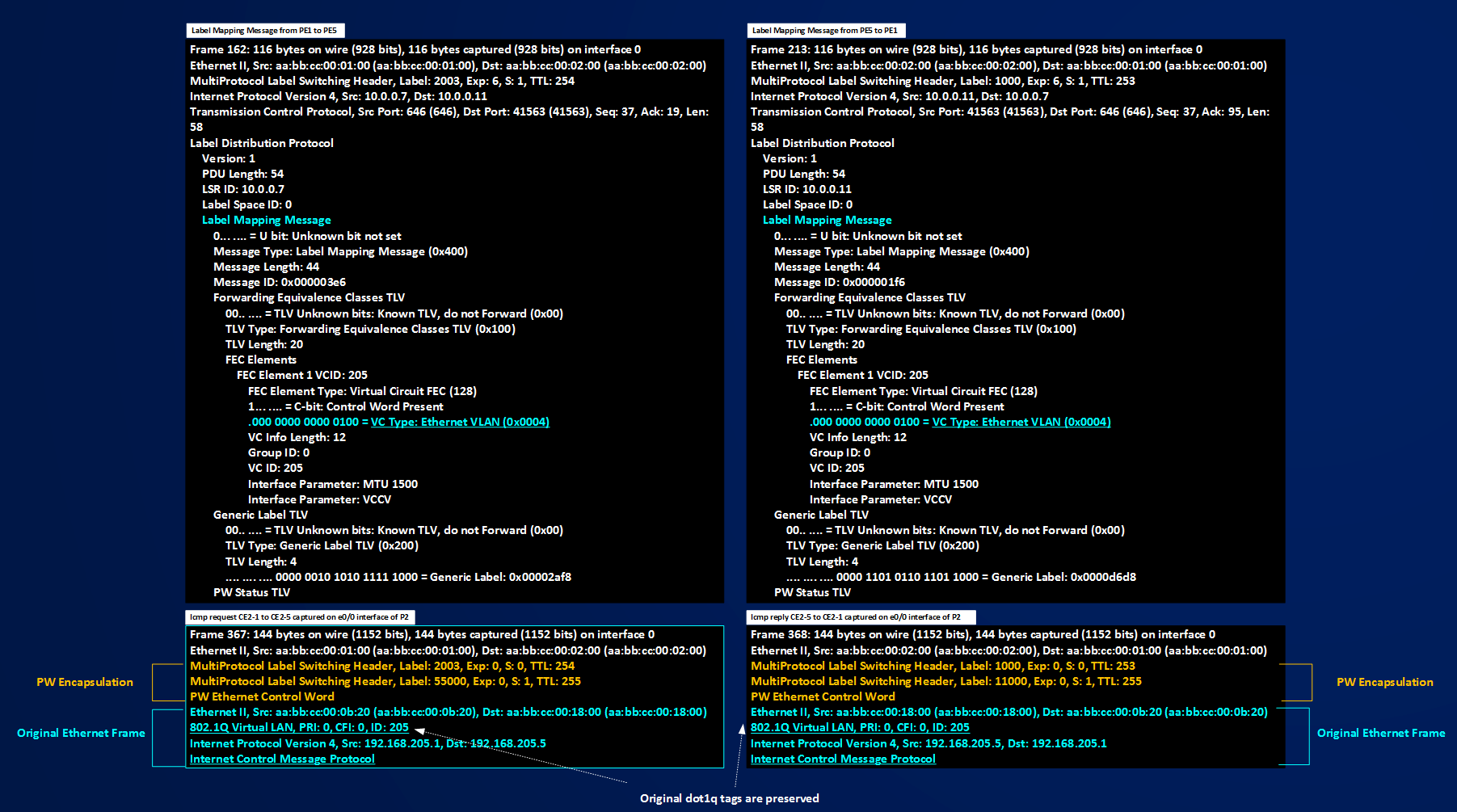
To recap I can say that we have a tool (pw-class) to control PW TYPE selection (0x0004 or 0x0005) and that based on where xconnect command is configured (physical interface or dot1q subinterfaces) tag may or may not be preserved (for PW TYPE 0x0005) and that tag are never removed (for PW TYPE 0x0004). Now I should have all the elements to speak about service-delimiting or not-service-delimiting tags. First of all I can say that a tag is service delimiting based on the type of service you want deploy, based on that then you can use pw-class to preserve or operate on the frames you receive or send out on/from a PE router, in other words you cannot configure a service-delimiting or not-service-delimiting tag, the only thing you can do on a frame is to leave intact the tags (if any are present), removing the first tag, rewriting the first tag, or adding a tag, then based on what you are trying to do you can use these operations to define a specific type of service. For example consider the scenarios described in the following figure.
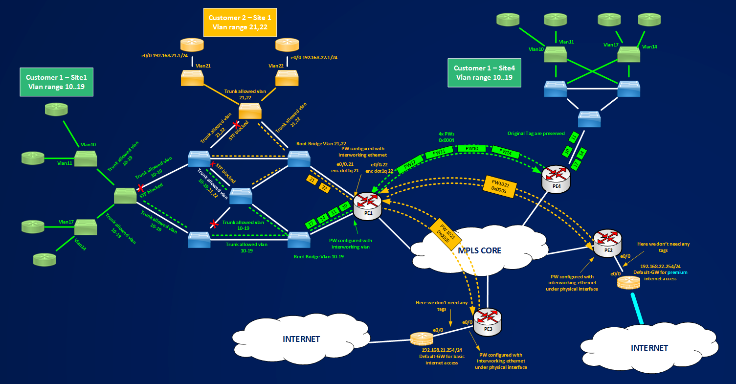
Figure shows two type of different services offered by the Service Provider to two of its customer. Customer 1 wants to extend its Vlans between its Sites 1 and 4, Customer 2 wants to have two different exits toward Internet for its Site1, one exit with Premium Internet Access and one with basic Internet Access. You, as small beginner Service Provider, don’t know too much about scaling Layer2 network (802.1ad, 802.1ah and so on.. maybe you will learn in the near future to expand your business..) then the best thing you think to offer is assigning different vlan ranges to each customer so you can distinguish between different customers inside your switched network, then you assign a different service role for each assigned vlan:
1] Customer 1: You tell customer that for what they pay, they can use ten Vlans in a range 10-19.
2] Customer 2: You tell customer that they will use 2 Vlans, 21 and 22, all devices that Customer 2 will connect to Vlan21 will receive basic internet access, Vlan22 will be serviced by premium internet access.
In these contexts, in case 1] you assign ten vlans to customer, but you don’t know how customer use this vlans, so we can say that you manage this vlans but not what they will service. In case 2], you manage vlans and also define the services. How can we define the tags? Tags are service delimiting or not? Tags are imposed by the service provider or by the customer? In these context there is no a best answer, in case 1] the tags are meaningful for PE1 because it uses every received tag to match a pseudowire that transports transparently the tag from one site to another, but are not meaningful from a service point of view, in case 2] a similar things happens, tags will be used to match a pseudowire but can be removed because they are not needed at remote site. This short example is to say that you have to understand very well the type of service you are going to deliver for a customer and, based on that, how you must configure the pseudowires for removing, preserving adding or rewriting a tag. You can read also errata of RFC4448 where service-delimiting and not-service-delimiting concepts are very well addressed.
To conclude this section I want to give some hints about Metro Ethernet Forum definitions and pseudowires. At wiki.mef.net you can find this defintion:
“VPWS (Virtual Private Wire Service) is the simplest form for enabling Ethernet services over MPLS. It is also known as ETHoMPLS (Ethernet over MPLS), or VLL (Virtual Leased Line). VPWS comprises point-to-point LSPs that carry Ethernet PWs (pseudowires) between LERs (Label Edge Routers).”
Then you have 4 names for identifying the same service: VPWS, ETHoMPLS, VLL or Ethernet Pseudowires. In my opinion, use the name you want, the important thing to remember is that Ethernet Pseudowires are made of 2 unidrectional LSPs and that they will give you a POINT-TO-POINT ETHERNET SERVICE.
This conclude this section about Ehternet Pseudowire, in the next section I will give some basic info about L2TPv3 Pseudowires, but using less words, because from a conceptual point of view, AToM and L2TPv3 give you the same service, that is transporting/extending Layer2 over MPLS or IP core, what changes are the signaling method and the encapsulation of the Layer2 frame.