In the previous section, I learned how a TE Tunnel is built and Signalled on the network. Now I need to figure out how can I use the built tunnels. To do this I restore all IGP (isis) metric to their default values and I revert all links to the same reservable bandwidth configuring ip rspv bandwidth percent 75 on all links between the core routers, then I have no constrains on bandwidth when a Tunnel headend builds a tunnel.
Now I create again a Tunnel1132 with POP1-C1 as Headend and POP3-C2 as Tailend:
POP1-C1#sh run int Tu1132 | b interface
interface Tunnel1132
description POP1-C1_to_POP3_C2
ip unnumbered Loopback0
tunnel mode mpls traffic-eng
tunnel destination 1.1.1.10
tunnel mpls traffic-eng priority 7 7
tunnel mpls traffic-eng bandwidth 3000
tunnel mpls traffic-eng path-option 10 dynamic
no routing dynamic
Here the link to the topology and here the link to all configured ip addresses
The path established by POP1-C1 is:
POP1-C1#show mpls traffic-eng tunnels Tunnel 1132
Name: POP1-C1_to_POP3_C2 (Tunnel1132) Destination: 1.1.1.10
Status:
Admin: up Oper: up Path: valid Signalling: connected
path option 10, type dynamic (Basis for Setup, path weight 30)
<– skipped output –>
InLabel : –
OutLabel : Ethernet1/3, 58
RSVP Signalling Info:
Src 1.1.1.5, Dst 1.1.1.10, Tun_Id 1132, Tun_Instance 3
RSVP Path Info:
My Address: 10.1.13.1
Explicit Route: 10.1.13.2 10.0.23.2 10.0.23.1 10.3.22.1
10.3.22.2 1.1.1.10
<– skipped output –>
Shortest Unconstrained Path Info:
Path Weight: 30 (TE)
Explicit Route: 10.1.13.1 10.1.13.2 10.0.23.2 10.0.23.1
10.3.22.1 10.3.22.2 1.1.1.10
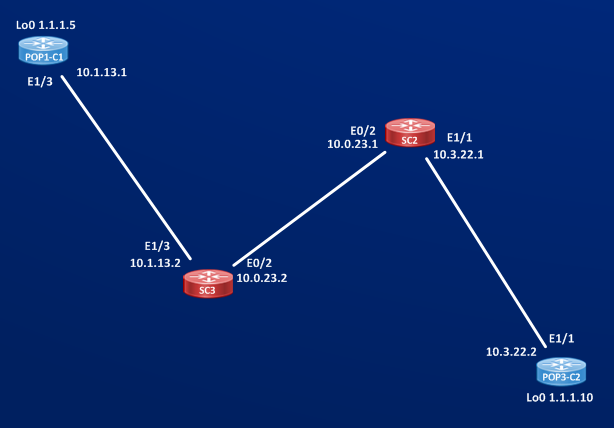
Built RSVP Path and Shortest Unconstrained Path are matching because all links allow to reserve at least 3 Mb/sec, then RSVP path collapses on IGP path.
Does creating a TE Tunnel interacts with Routing Table of the Headend router (POP1-C1) or with routing table of any other routers? Let’s check:
POP1-C1#show ip route | i Tunnel
POP1-C1#
No route is learned via Tunnel interface. Creating a Tunnel doesn’t install any route in the Headend Router or in any other router of the network. But to send traffic on an interface being a Tunnel or not I need to have a next-hop on that interface. So I’m missing something to use the just created Tunnel.
Tracing one of the destination behind the Tunnel Tail (POP3-C2) for example Lo0 of A3-2 switch (1.1.1.18)
POP1-C1#traceroute 1.1.1.18 source 1.1.1.5 probe 2
Type escape sequence to abort.
Tracing the route to 1.1.1.18
VRF info: (vrf in name/id, vrf out name/id)
1 10.1.11.1 [MPLS: Label 67 Exp 0] 2 msec
10.1.13.2 [MPLS: Label 68 Exp 0] 5 msec
2 10.0.12.2 [MPLS: Label 68 Exp 0] 5 msec
10.0.34.2 [MPLS: Label 67 Exp 0] 4 msec
3 10.3.12.1 [MPLS: Label 68 Exp 0] 4 msec
10.3.14.1 [MPLS: Label 68 Exp 0] 5 msec
4 192.170.12.2 4 msec 4 msec
Looking at the trace it’s clear that packet never follows the path calculated by the Tunnel even if TE path matches Shortest Unconstrained Path, looking at the second probe of the trace I can see that after reaching SC3 (10.1.13.2) the packet is sent to SC4 (10.0.34.2) and not to SC2 (10.0.23.1) this is normal cef load sharing made on SC3:
SC3#show ip cef 1.1.1.18 detail
1.1.1.18/32, epoch 0, per-destination sharing
local label info: global/68
nexthop 10.0.23.1 Ethernet0/2 label 68
nexthop 10.0.34.2 Ethernet0/0 label 67
SC3#show ip cef exact-route 1.1.1.5 1.1.1.18
1.1.1.5 -> 1.1.1.18 => label 67 TAG adj out of Ethernet0/0, addr 10.0.34.2
SC3#show ip cef exact-route 1.1.1.6 1.1.1.18
1.1.1.6 -> 1.1.1.18 => label 68 TAG adj out of Ethernet0/2, addr 10.0.23.1
If the packet came with source 1.1.1.6 instead of 1.1.1.5 it would be routed to SC2, but this has nothing to do with the Tunnel.
This short deviation is to enforce the concept that a TE path it is only a control plane factor until we force the traffic to flow through the TE Tunnel and then we program an entry in the cef table that has Tunnel1132 as exit interface.
Now, generally speaking to steer traffic down an interface we have these option:
1) Making the interface part of some dynamic routing
2) Using static route
3) Using Policy-Based Routing
With Traffic Engineering we have another option ==> AUTOROUTE.
Look at the configured tunnel interface:
POP1-C1#sh run int Tunnel1132 | b interface
interface Tunnel1132
description POP1-C1_to_POP3_C2
ip unnumbered Loopback0
tunnel mode mpls traffic-eng
tunnel destination 1.1.1.10
tunnel mpls traffic-eng priority 7 7
tunnel mpls traffic-eng bandwidth 3000
tunnel mpls traffic-eng path-option 10 dynamic
no routing dynamic
The last command “no routing dynamic” is set by default by the IOS, I’ve not configured this command. Why IOS does this? Because if we think to enable dynamic routing on Tunnel interface we will do a sort of redundant not-scalable operation, for example I could think to enable isis on the Tunnel interface, what does this gives me that I haven’t already? Supposing that it works (remember a TE path is a unidirectional path, then my isis hello would go from POP1-C1 to POP3-C2 but I need a TE path in the opposite direction to receive hello packets from POP3-C2) all routers have already all the link state topology information about the newtork, so why do we need to replicate one more time this info on the Tunnel interfaces? Then we can exclude 1) because is not efficient and not scalable.
About 2) and 3) we have the same limitation we have with normal IP routing, static routing and policy based routing are not too much scalable. Anyway, let’s see if in this scenario steering traffic down the Tunnel is simple or not. I configure a static route to force traffic destined to Vlan31-PoP3 to flow down the Tunnel the operation seems to be simple:
POP1-C1#sh run | s ip route 31
ip route 31.31.31.0 255.255.255.0 Tunnel1132
POP1-C1#show ip cef 31.31.31.0 detail
31.31.31.0/24, epoch 0, flags attached
local label info: global/59
attached to Tunnel1132
With this static route I put Tunnel interface in the routing table of POP1-C1, but since access-switch of my network are receiving isis route via redisribution from level2 database
POP1-C1#show run | s r i | red
redistribute isis ip level-2 into level-1 route-map LVL2-TO-LVL1
setting this static route to the tunnel interface remove the isis level2 learned route (about network 31.31.31.0/24) off POP1-C1’s routing table and then I’m redistributing this route via isis level 1 no more:
A1-1#show ip route 31.31.31.0
Routing entry for 31.31.31.0/24
Known via “isis”, distance 115, metric 50, type inter area
Redistributing via isis ACCESS
Last update from 192.168.21.1 on Ethernet0/1, 00:14:31 ago
Routing Descriptor Blocks:
* 192.168.21.1, from 1.1.1.6, 00:14:31 ago, via Ethernet0/1
Route metric is 50, traffic share count is 1
I can see that A1-1 has now only one next-hop that is POP1-C2, if now I send traffic destined to 31.31.31.1 from A1-1 there is no chance that this traffic flow trough the Tunnel1132 of POP1-C1:
A1-1#traceroute
Protocol [ip]:
Target IP address: 31.31.31.1
Source address: 11.11.11.1
Numeric display [n]:
Timeout in seconds [3]:
Probe count [3]:
Minimum Time to Live [1]:
Maximum Time to Live [30]:
Port Number [33434]:
Loose, Strict, Record, Timestamp, Verbose[none]:
Type escape sequence to abort.
Tracing the route to 31.31.31.1
VRF info: (vrf in name/id, vrf out name/id)
1 192.168.21.1 5 msec 5 msec 4 msec
2 10.3.14.1 [MPLS: Label 19 Exp 0] 5 msec 6 msec 6 msec
3 192.170.12.2 7 msec 6 msec 5 msec
4 31.31.31.1 6 msec 5 msec 5 msec
Then I could CAREFULLY redistribute the static route into isis level-1 only but I need to avoid loop in doing this (try yourself if you have time to configure a redistribution solution that let you use the static route to Tunnel interface on POP1-C1 and steer the traffic from access-switch to the Tunnel, is not a so easy task).
What I’m trying to say here is that design and placement of the tunnels should be carefully studied before implementing it. For example a simpler solution here could be to extend the tunnel to the access devices but to do this you have to cross level-1/level-2 isis domain and then again you must be careful because MPLS TE crossing different isis level domain or OSPF area has some restrictions too.
Now, it seems that we can “simply build” some TE tunnels but is not so easy to steer traffic down them. Here comes AUTOROUTE features that let us to leave away static routing and or policy routing.
What does autoroute exactly mean? Autoroute can be considered a feature of MPLS TE that integrates the presence of Tunnel interfaces with the IGP that is running on the network. We know that creating and activating an interface on a router is not enough to send traffic down to that interface, we need a routing protocol running on that interface and to learn routes via that interface.
“autoroute tells the router to consider Headend and Tailend as if they were directly connected by the Tunnnel link and force the router to send traffic destined to the Tailend or traffic destined to devices beihind the Tailend down the tunnel interface.” Reference “Traffic engineering with MPLS”
To be honest first time I read this, no clear picture came to my mind about how this autoroute works.
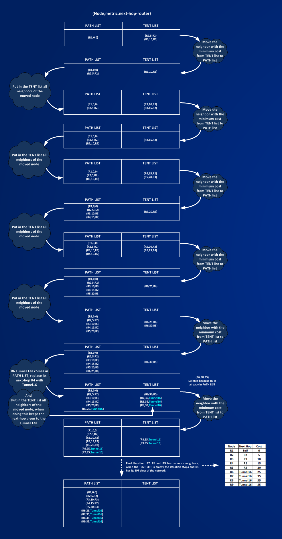
Practically speaking, Autoroute modifies the Shortest Path First algorithm used by the IGP (isis in this case), then it modifies the routing table of the router placing the tunnel in the IGP path. How does the hell it works? To understand this I will do a little SPF computation on a smaller test network:
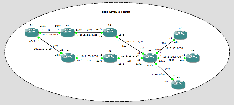
How router POP1-C1 builds its SPF path to the tailend POP3-C2? Making SPF by own hand is very boring, it’s more funny when routers do it by themselves, anyway to understand autoroute it’s worth to do it at least one time.
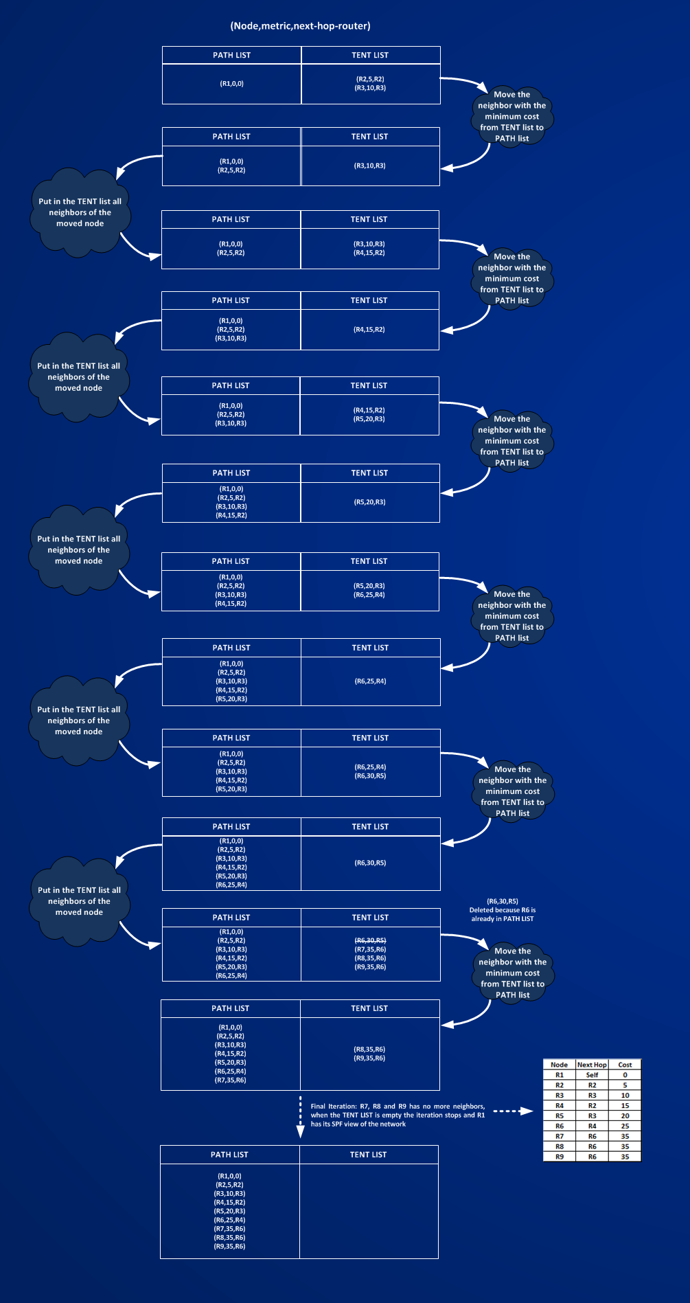
All isis link have a cost of 10 but link R1-to-R2 that has isis cost of 5. To start put the headend router (the one who is calculating the SPF) in a list called PATH LIST and its neighbors in a TENT LIST, then follow the picture:
Now I activate first a TE Tunnel without AUTOROUTE on R1 (Headend) to R6 (Tailend):
R1#sh run int Tu16 | b interface
interface Tunnel16
description R1-to-R6
ip unnumbered Loopback0
load-interval 30
tunnel mode mpls traffic-eng
tunnel destination 6.6.6.6
tunnel mpls traffic-eng priority 7 7
tunnel mpls traffic-eng bandwidth 3000
tunnel mpls traffic-eng path-option 10 dynamic
no routing dynamic
Then I configure autoroute on the tunnel,
R1#sh run int Tu16 | b interface
interface Tunnel16
description R1-to-R6
ip unnumbered Loopback0
load-interval 30
tunnel mode mpls traffic-eng
tunnel destination 6.6.6.6
tunnel mpls traffic-eng priority 7 7
tunnel mpls traffic-eng bandwidth 3000
tunnel mpls traffic-eng path-option 10 dynamic
tunnel mpls traffic-eng autoroute announce
no routing dynamic
let’s check how the routing table changes on R1:
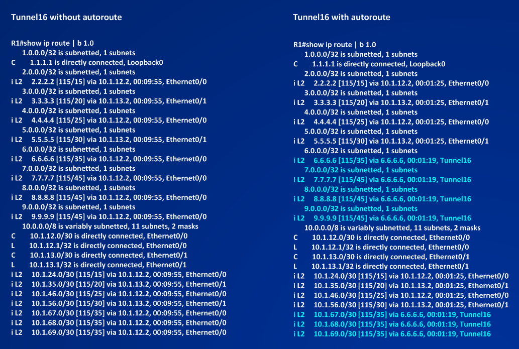 You can see that AUTOROUTE puts interface Tunnel16 in R1’s routing table. Reading the new routing table I can note that the tunnel tail and all the routers behind the tunnel tail are now reachable via Tunnel16.
Tracing a destination behind R6 before configuring autoroute:
R1#traceroute 8.8.8.8 source 1.1.1.1
Type escape sequence to abort.
Tracing the route to 8.8.8.8
VRF info: (vrf in name/id, vrf out name/id)
1 10.1.12.2 [MPLS: Label 202 Exp 0] 8 msec 7 msec 6 msec
2 10.1.24.2 [MPLS: Label 405 Exp 0] 6 msec 7 msec 7 msec
3 10.1.46.2 [MPLS: Label 604 Exp 0] 6 msec 6 msec 7 msec
4 10.1.68.2 8 msec 7 msec 6 msec
Tracing a destination behind R6 after configuring autoroute:
R1#traceroute 8.8.8.8 source 1.1.1.1
Type escape sequence to abort.
Tracing the route to 8.8.8.8
VRF info: (vrf in name/id, vrf out name/id)
1 10.1.12.2 [MPLS: Label 215 Exp 0] 7 msec 8 msec 5 msec
2 10.1.24.2 [MPLS: Label 415 Exp 0] 7 msec 6 msec 6 msec
3 10.1.46.2 7 msec 7 msec 6 msec
4 10.1.68.2 7 msec 6 msec 15 msec
It’s worth to do some more comments about things change with autoroute.
First look at the metric to reach network 8.8.8.8:
R1#show ip route 8.8.8.8
Routing entry for 8.8.8.8/32
Known via “isis”, distance 115, metric 45, type level-2
Redistributing via isis CORE
Last update from 6.6.6.6 on Tunnel16, 00:07:22 ago
Routing Descriptor Blocks:
* 6.6.6.6, from 8.8.8.8, 00:07:22 ago, via Tunnel16
Route metric is 45, traffic share count is 1
R6#show ip route 8.8.8.8
Routing entry for 8.8.8.8/32
Known via “isis”, distance 115, metric 20, type level-2
Redistributing via isis CORE
Last update from 10.1.68.2 on Ethernet0/1, 00:55:08 ago
Routing Descriptor Blocks:
* 10.1.68.2, from 8.8.8.8, 00:55:08 ago, via Ethernet0/1
Route metric is 20, traffic share count is 1
We exit from Tunnel16, then we could expect that since Tunnel16 is a directly interface of R1 the metric will be 20 (0+20(R6->R8 metric)). The wrong assumption here is that Tunnel16 ia a directly connected interface of R1, first this is not true because Tunnel16 is an unnumbered interface:
R1#sh ip route connected | b 1.0
1.0.0.0/32 is subnetted, 1 subnets
C 1.1.1.1 is directly connected, Loopback0
10.0.0.0/8 is variably subnetted, 11 subnets, 2 masks
C 10.1.12.0/30 is directly connected, Ethernet0/0
L 10.1.12.1/32 is directly connected, Ethernet0/0
C 10.1.13.0/30 is directly connected, Ethernet0/1
L 10.1.13.1/32 is directly connected, Ethernet0/1
second and most important AUTOROUTE keeps the shortest IGP metric to the Tunnel Tail as metric for the Tunnel, here you can find the process of the modified SPF calculation when autoroute is working:
Second, let’s compare (see also above) the two traces without AUTOROUTE and with AUTOROUTE:
Without AUTOROUTE
R1#traceroute 8.8.8.8 source 1.1.1.1
Type escape sequence to abort.
Tracing the route to 8.8.8.8
VRF info: (vrf in name/id, vrf out name/id)
1 10.1.12.2 [MPLS: Label 202 Exp 0] 8 msec 7 msec 6 msec
2 10.1.24.2 [MPLS: Label 405 Exp 0] 6 msec 7 msec 7 msec
3 10.1.46.2 [MPLS: Label 604 Exp 0] 6 msec 6 msec 7 msec
4 10.1.68.2 8 msec 7 msec 6 msec
With AUTOROUTE
R1#traceroute 8.8.8.8 source 1.1.1.1
Type escape sequence to abort.
Tracing the route to 8.8.8.8
VRF info: (vrf in name/id, vrf out name/id)
1 10.1.12.2 [MPLS: Label 215 Exp 0] 7 msec 8 msec 5 msec
2 10.1.24.2 [MPLS: Label 415 Exp 0] 7 msec 6 msec 6 msec
3 10.1.46.2 7 msec 7 msec 6 msec
4 10.1.68.2 7 msec 6 msec 15 msec
To help in better reading the label assignment I constrained the label space of each routers configuring these commands:
R1:mpls label range 100 199
R2:mpls label range 200 299
R3:mpls label range 300 399
R4:mpls label range 400 499
R5:mpls label range 500 599
R6:mpls label range 600 699
R7:mpls label range 700 799
R8:mpls label range 800 899
R9:mpls label range 900 999
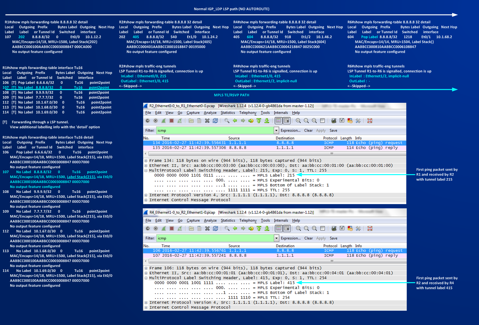
We can see that the crossed devices are exactly the same (because TE PATH collapses on IGP PATH), there is one difference that consists in the labels used to switch the traffic. In the first case (no AUTOROUTE) the used labels are 202,405,604 – in the second one (AUTOROUTE) the label used are 215,415. The difference is that without aoutoroute we are not using tunnel to send traffic to 8.8.8.8, with autoroute I’m using Tunnel16 then the labels are those that are defined and signalled by RSVP process when Tunnel is set up. In the first case we have three labels in the path because is R6 that works as penultimate-hop router (R8 announce an implicit-null for 8.8.8.8/32), in the second case R4 is the penultimate-hop router, because is R6 (the Tailend) that signals an implicit-null for Tunnel16. Following picture should give an idea of the labels and of the mpls encapsulation.
Then, so far I learned the basic idea about:
1] How a TE Tunnel is configured and built
2] How a TE Tunnel is signalled on the network
3] How to forward traffic down a TE Tunnel interface (static routing, policy routing, Autoroute)
In next section I wanna go deeper in how an MPLS TE Tunnel can be manually built and how Constrained Shortest Path First can be influenced by links attributes, administrative weights and some notes on load sharing between IGP path and TE paths.
Move to next section >> Influencing MPLS-TE CSPF